Tool holder for tangential cutting insert

a tool holder and insert technology, applied in the field of tool holders, can solve the problems of difficult arrangement of tangential cutting inserts, impairing the chip flow on the side surfaces, etc., and achieve the effect of protecting against damage and easy control of the cutting geometry between the main lip and the workpi

Active Publication Date: 2018-07-31
KENNAMETAL INC
View PDF43 Cites 0 Cited by
  • Summary
  • Abstract
  • Description
  • Claims
  • Application Information

AI Technical Summary

Benefits of technology

[0007]In order to achieve this object, in the case of a tool holder of the type mentioned at the beginning, the invention provides that the bottom surface is quadrangular in plan view and has a raised supporting region which has two supporting surfaces, positioned obliquely with respect to one another, for the cutting insert. The obliquely positioned supporting surfaces come into contact with a side surface of the cutting insert, such that the forces acting on the cutting insert can be transmitted reliably into the tool holder. In this case, self-centering of the cutting insert on the supporting surfaces occurs. Since the bottom surface is quadrangular and its geometry thus corresponds in principle with the geometry of the side surfaces of the cutting insert, the cutting edges of the cutting insert, which are located directly opposite the supporting region, can additionally be protected from damage by chips. For this purpose, the bottom surface can be configured in a slightly larger manner than the side surfaces of the cutting insert with little effort, such that the bottom surface protrudes slightly beyond the cutting insert.
[0018]Provision is preferably made for the cutting insert to have a plurality of cutting edges, with the cutting edges that face the bottom surface being arranged at a distance from the bottom surface. This ensures that the cutting edges cannot come into contact with the bottom surface of the receptacle, such that in this respect, too, the cutting edges are protected against damage. It is preferably provided that the transition portion, the front portion and / or the rear portion extend in a straight line. In this way, the cutting geometry between the main lip and the workpiece can be controlled easily.

Problems solved by technology

The complex shape of the side surfaces makes it difficult to arrange the tangential cutting insert in the receptacle of the tool holder such that the forces that arise during cutting are introduced into the tool holder in the desired manner.
In addition to the fact that the protrusions complicate the production of the tangential cutting insert, they impair the chip flow on the side surfaces which represent the rake faces of the cutting insert.

Method used


Image

  • Tool holder for tangential cutting insert
  • Tool holder for tangential cutting insert
  • Tool holder for tangential cutting insert

Examples


Embodiment Construction

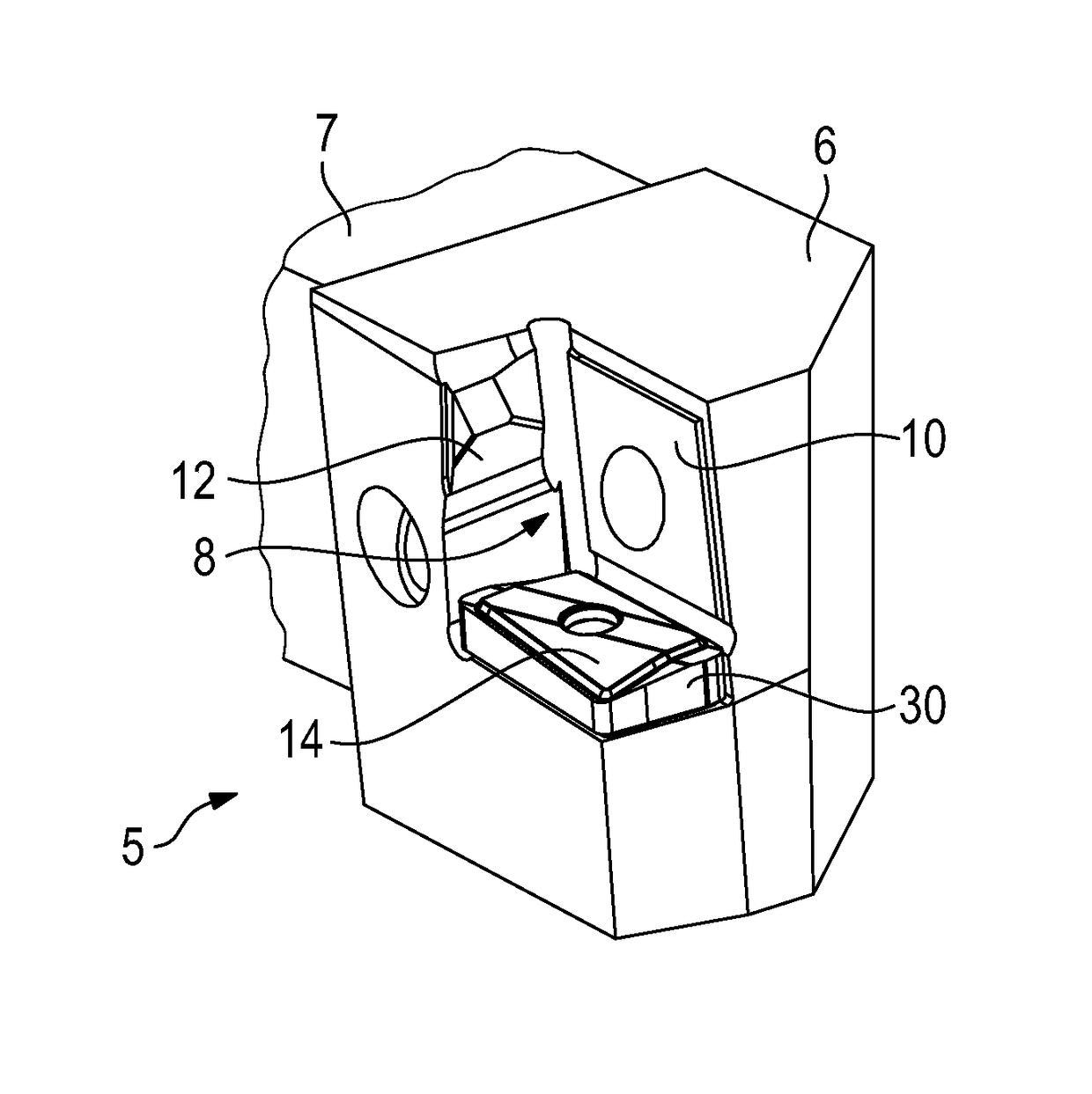
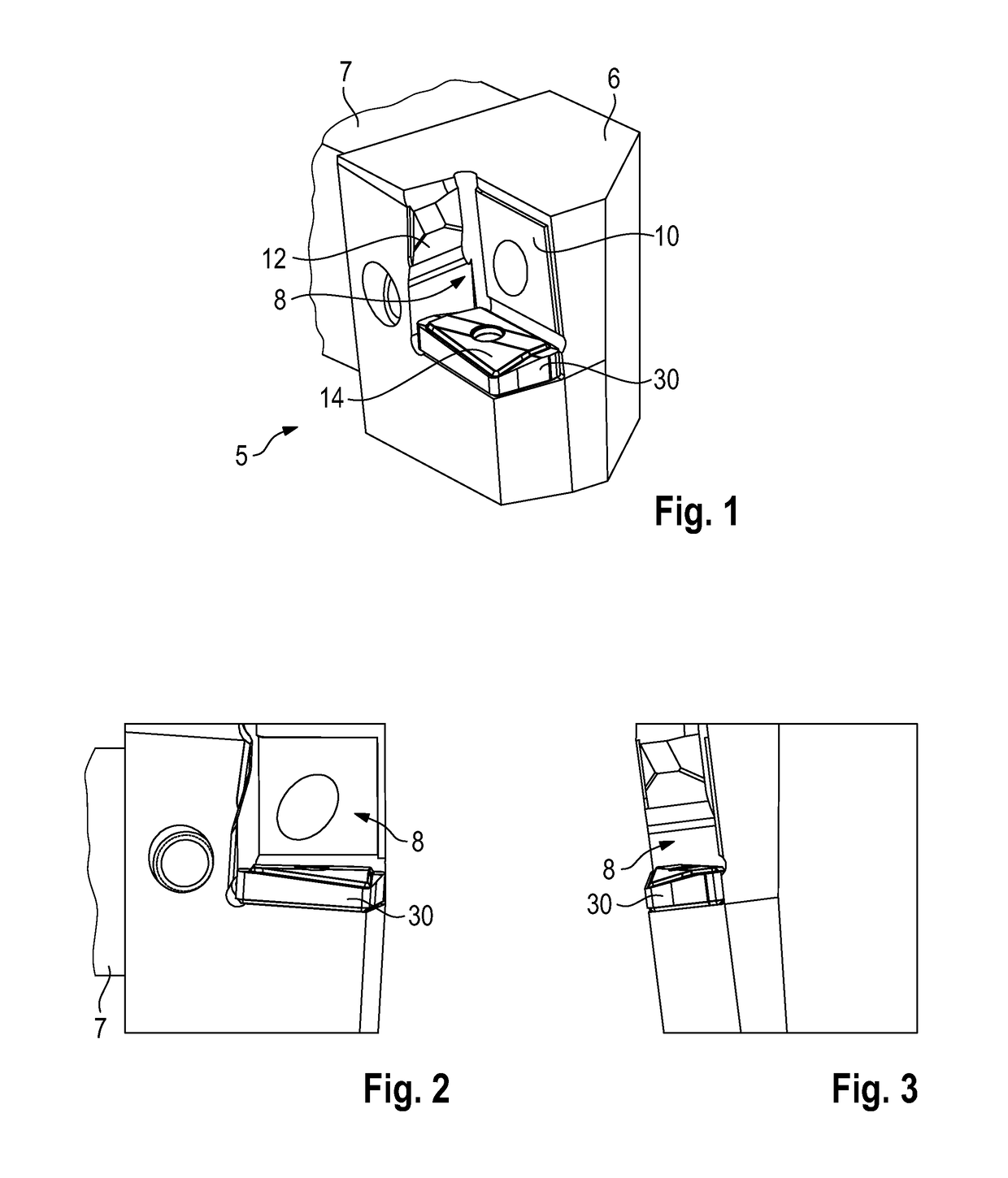
[0037]FIGS. 1 to 14 show a tool holder 5 according to a first embodiment. It contains a holding portion 6 which is fitted on a shank 7 which is shown broken away here. The shank 7 can be mounted on a tool holder carrier.

[0038]The holding portion 6 of the tool holder 5 is provided with a receptacle 8 in which a cutting insert 9 (see FIGS. 10 to 14) can be fitted.

[0039]The receptacle 8 contains a lateral bearing surface 10, a rear bearing surface 12 and a bottom surface 14. The surfaces 10, 12, 14 serve to support the cutting insert 9.

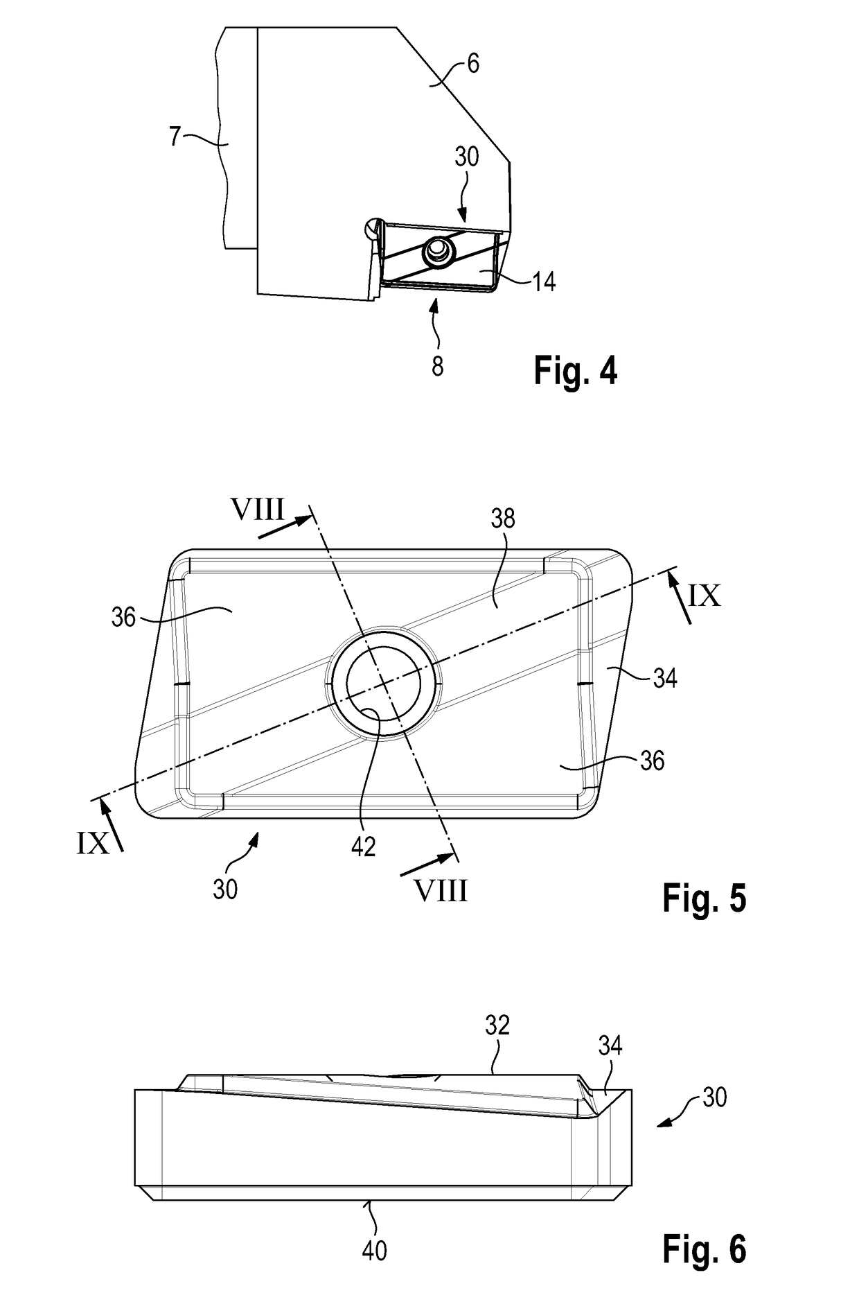
[0040]The cutting insert 9 is a tangential cutting insert as is known in principle from DE 10 2007 022 536 A1. It has two base surfaces 20 which have a generally square shape and are rotated with respect to one another. Provided between the peripheries of the base surfaces 20 are four side surfaces 22, with each side surface forming two main lips 24 with the base surfaces. A secondary lip 26 is formed in each case at the transition between adjacent side ...


PUM


Abstract

In the case of a tool holder having a receptacle for a cutting insert, in particular a tangential cutting insert having eight lips, having a lateral bearing surface, a rear bearing surface and a bottom surface, the bottom surface is quadrangular in plan view and has a raised supporting region which has two supporting surfaces, positioned obliquely with respect to one another, for the cutting insert.

Description

CLAIM TO PRIORITY[0001]This application is the National Stage of International Application No. PCT / IB2013 / 002622, filed on Aug. 27, 2013, the entire contents of which is incorporated herein by reference.FIELD OF THE INVENTION[0002]The invention relates to a tool holder having a receptacle for a cutting insert, in particular a tangential cutting insert having eight lips, having a lateral bearing surface, a rear bearing surface and a bottom surface. The invention furthermore relates to an assembly having such a tool holder and a tangential cutting insert which is fitted in the receptacle of the tool holder and rests on the bottom surface.BACKGROUND OF THE INVENTION[0003]Tangential cutting inserts are known from the prior art. An example can be found in DE 10 2007 022 536 A1. The tangential cutting insert has two opposite, similar and substantially square bottom surfaces which are rotated with respect to one another. Formed along the outer peripheries of the bottom surfaces are four si...

Claims


Application Information

Patent Timeline
Patent Type & Authority Patents(United States)
IPC IPC(8): B23B27/16
CPCB23B27/1622B23B2200/0471B23B2200/163B23B2200/369Y10T407/22B23B2205/12B23B2205/16B23B2228/24B23B2200/3681B23B27/1681B23B29/04B23B27/1618B23C5/2298B23C5/2239
Inventor KAUFMANN, IGORMOHIDEEN ABDUL, ANWAR SADAT
Owner KENNAMETAL INC
Why Eureka
Try Eureka