Debris removal device and debris removal method

a technology of debris removal and debris, which is applied in the direction of cosmonautic components, cosmonautic parts, cosmonautic vehicles, etc., can solve the problems of forming debris (space junk), leaving as debris, and often leaving artificial satellites in orbit, so as to reduce the reaction force and reduce the necessary kinetic energy

Active Publication Date: 2017-04-27
IHI CORP
View PDF0 Cites 12 Cited by
  • Summary
  • Abstract
  • Description
  • Claims
  • Application Information

AI Technical Summary

Benefits of technology

[0009]An object of the present disclosure is to provide a debris removal device and a debris removal method, which are capable of reducing the reaction force generated at the shooting of the harpoon, and are capable of capturing debris precisely.
[0011]According to this debris removal device, the harpoon is not shot at a distant point, but the shooting angle of the harpoon is adjusted by causing the debris capture device to approach the debris, and by bringing the guide member into contact with the surface of the debris, so that the harpoon can be shot at an appropriate shooting angle, at a position near the surface of the debris. For this reason, it is possible to reduce the necessary kinetic energy in shooting at the debris, and the reaction force can be reduced. In addition, since the harpoon is shot after the shooting angle is adjusted at a position near the debris, the possibility that the harpoon will miss the debris, be rebounded, or completely penetrate through the debris can be reduced, so that the debris can be captured precisely.

Problems solved by technology

When the artificial satellites break down and do not function anymore, or when they finish their assignments and reach the end of their service life, the artificial satellites are often left in orbit, forming debris (space junk).
In addition, the wreckage of rockets and the like used for launching artificial satellites and the like are also left as debris in orbit.
The debris are attracted by the terrestrial gravitation, and eventually fall and disappear; however, the natural falling requires long periods of time, and it is not efficient.
Accordingly, excessive reaction force is generated in the satellite from which the harpoon is shot, and hence the strength of the satellite has to be increased, which causes an increase in weight.
In addition, another problem would be presented in which debris cannot be captured precisely, because the harpoon would miss the debris, the harpoon would be rebounded by the surface of the debris, or the harpoon would penetrate completely through the debris.

Method used


Image

  • Debris removal device and debris removal method
  • Debris removal device and debris removal method
  • Debris removal device and debris removal method

Examples


first embodiment

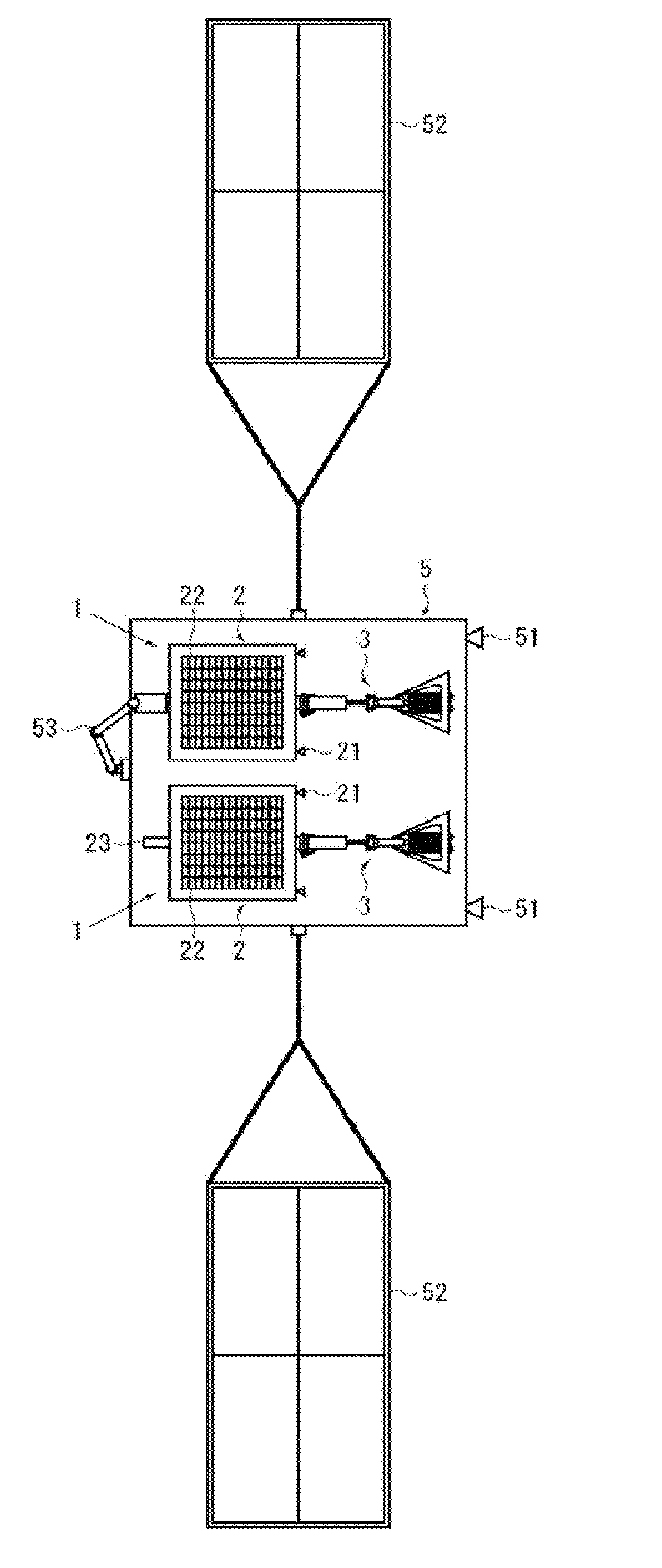
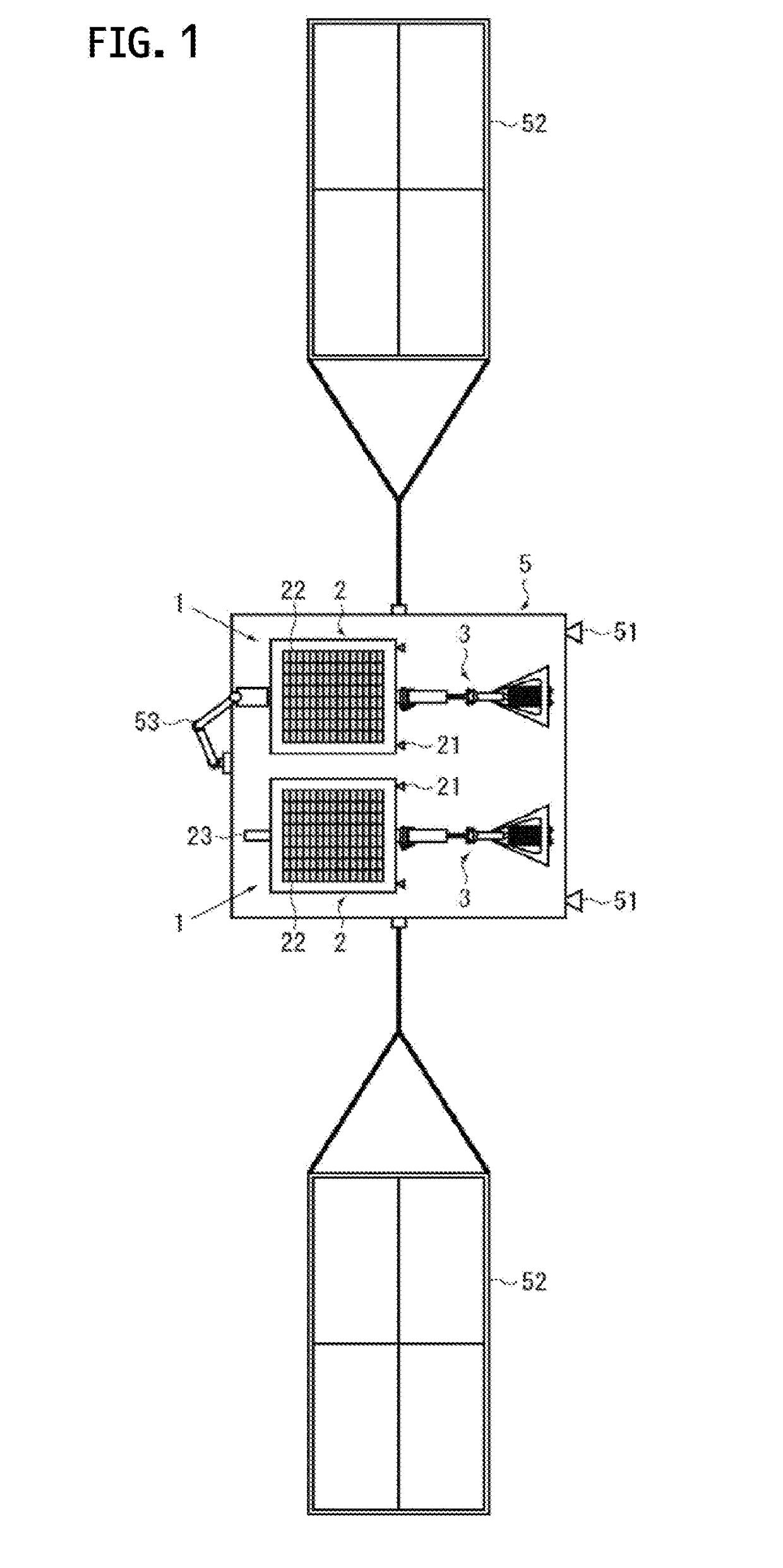
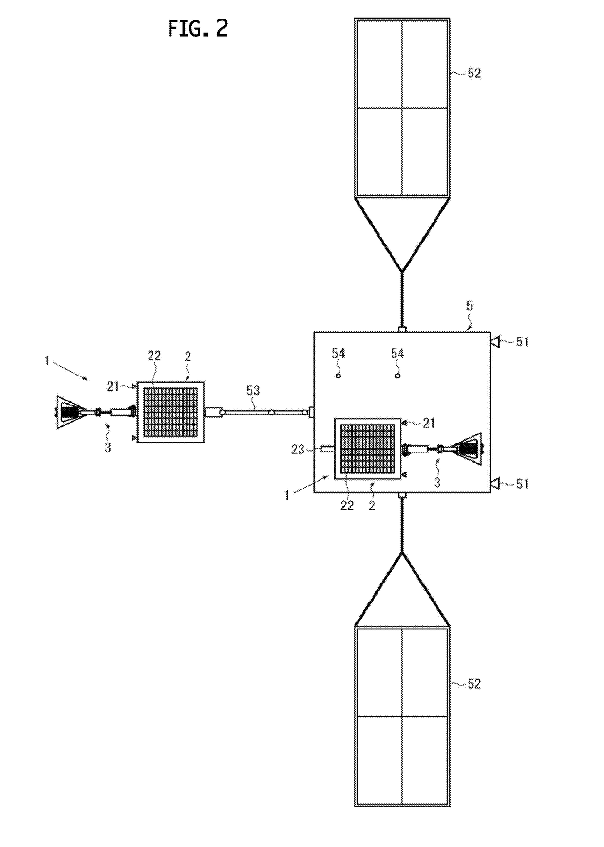
[0024]Hereinafter, several embodiments of the present disclosure are described by using FIGS. 1 to 10. Here, FIG. 1 is a top view showing debris removal devices according to the present disclosure, showing a state where the debris removal devices are accommodated in a mother ship. FIG. 2 shows a state where a debris removal device shown in FIG. 1 is assuming a capturing attitude. FIG. 3 is a partial lateral cross-sectional view showing a debris capture device of a debris removal device shown in FIG. 1.

[0025]A debris removal device 1 according to a first embodiment of the present disclosure is a device that captures debris drifting in outer space, and removes the debris from orbit. As shown in FIGS. 1 to 3, the debris removal device 1 includes: an end mass 2 adapted to be capable of approaching debris X to be removed; a debris capture device 3 separably-mounted on the end mass 2; and a tether 4 connecting the debris capture device 3 and the end mass 2 to each other. The debris captur...

second embodiment

[0061]In the second embodiment shown in FIGS. 8A and 8B, the end mass 2 includes a support device 24 that supports the shooting device 32. The support device 24 includes, for example, a pair of frames 24a each rotatably-connected to the end mass 2 via a hinge 24c, and a restraining device 24b that restrains the front end portions of both of the frames 24a to the shooting device 32.

[0062]The pair of frames 24a are provided at positions facing each other, with the shooting device 32 interposed therebetween, and holding the shooting device 32 therebetween. Each of the frames 24a has, for example, an A-letter shape as shown in FIG. 8B, and two-leg portions are each connected to the end mass 2. The restraining device 24b includes, for example, a wire that restrains the front end portions of the pair of frames 24a in a state of being in contact with the shooting device 32 (specifically, the cylinder 32a), and a wire cutter that cuts the wire. Note that the shape of the frames 24a and the ...

third embodiment

[0065]In the third embodiment shown in FIG. 9A, a buffer 6 is provided which reduces the impact generated when the debris capture device 3 comes into contact with the surface of the debris X. The buffer 6 is provided, for example, at an intermediate portion of a tubular body constituting the tether release port 2a of the end mass 2, and includes a link mechanism, for example. The link mechanism links a front section and a rear section formed by, for example, dividing the tubular body of the tether release port 2a into two front and rear pieces. Here, the buffer 6 is shown which includes the two links, but the number of the links is not limited to that shown in the drawing. In addition, the buffer 6 may be one utilizing an elastic body such as a spring or rubber, or a component such as a bellows instead of the link mechanism.

[0066]In reference to the debris removal device 1 according to the third embodiment, for example, the frames 24a can be retracted at a stage of the approaching s...


PUM


Abstract

A debris removal device includes: an end mass adapted to approach debris to be removed; a debris capture device separably-mounted on the end mass; and a tether connecting the debris capture device and the end mass to each other. The debris capture device includes a harpoon adapted to penetrate into the debris, a shooting device adapted to shoot the harpoon, a guide member positioned to come into contact with the surface of the debris to adjust the shooting angle of the harpoon with respect to the surface of the debris, and a switch that sends the shooting signal to the shooting device. When the harpoon is penetrated into the debris, the end mass is separated from the debris capture device, and the tether is released into outer space.

Description

CROSS REFERENCE TO RELATED APPLICATIONS[0001]This application is a continuation application of International Application No. PCT / JP2015 / 077537 filed on Sep. 29, 2015, which claims priority to Japanese Patent Application No. 2014-199569 filed on Sep. 30, 2014, the entire contents of which are incorporated herein by reference.BACKGROUND[0002]Technical Field[0003]The present disclosure relates to a debris removal device and a debris removal method, and particularly relates to a debris removal device and a debris removal method which are suitable for removing debris drifting in outer space, such as satellites and rockets which are not used anymore and are orbiting the Earth.[0004]Description of the Related Art[0005]Currently, artificial satellites, such as military satellites, communications satellites, scientific satellites, observation satellites, and navigation satellites, are orbiting for various purposes. When the artificial satellites break down and do not function anymore, or whe...

Claims


Application Information

Patent Timeline
Patent Type & Authority Applications(United States)
IPC IPC(8): B64G1/64
CPCB64G1/648B64G1/64
Inventor MORI, HATSUOIZUMIYAMA, TAKUHASHIMOTO, KOZUEKAWAMOTO, SATOMIHIRAKO, KEIICHI
Owner IHI CORP
Why Eureka
Try Eureka