Eureka AIR delivers breakthrough ideas for toughest innovation challenges, trusted by R&D personnel around the world.

Vehicular lamp

Active Publication Date: 2017-04-27
STANLEY ELECTRIC CO LTD
View PDF0 Cites 6 Cited by
  • Summary
  • Abstract
  • Description
  • Claims
  • Application Information

AI Technical Summary

Benefits of technology

The patent text describes a new design for vehicular lamps that aims to improve driving safety. The lamps provide linear light distribution patterns that include non-light-emitting zones between them. These zones have different light-emitting times and cycles depending on the distance between the vehicle and a front vehicle, allowing the driver to confirm the linear distribution patterns with a door mirror and safely turn the vehicle around. The lamps are simple in structure and can provide various linear light distribution patterns for better driver assistance. The disclosed subject matter thus provides a simple solution for safely driving and improving driving safety for drivers of the forward vehicle.

Problems solved by technology

When drivers turn a vehicle around while the drivers steer the vehicle, the vehicle is subject to a rear-end collision by a rearward vehicle, which approaches from a rearward direction of the vehicle, especially on a road with poor visibility at night.
However, the conventional drive assist apparatus need at least controllers such as the image processing controller and the display controller in addition to the camera, and therefore may be subject to a complex structure.
Additionally, the drivers may not afford a watch with the monitor 13 because the drivers may generally confirm surrounding conditions with a door mirror when the drivers turn the subject vehicle around.
Accordingly, drivers of a rear vehicle, which moves toward the subject vehicle, may not also drive responsibly at ease.

Method used


Image

  • Vehicular lamp
  • Vehicular lamp
  • Vehicular lamp

Examples


Embodiment Construction

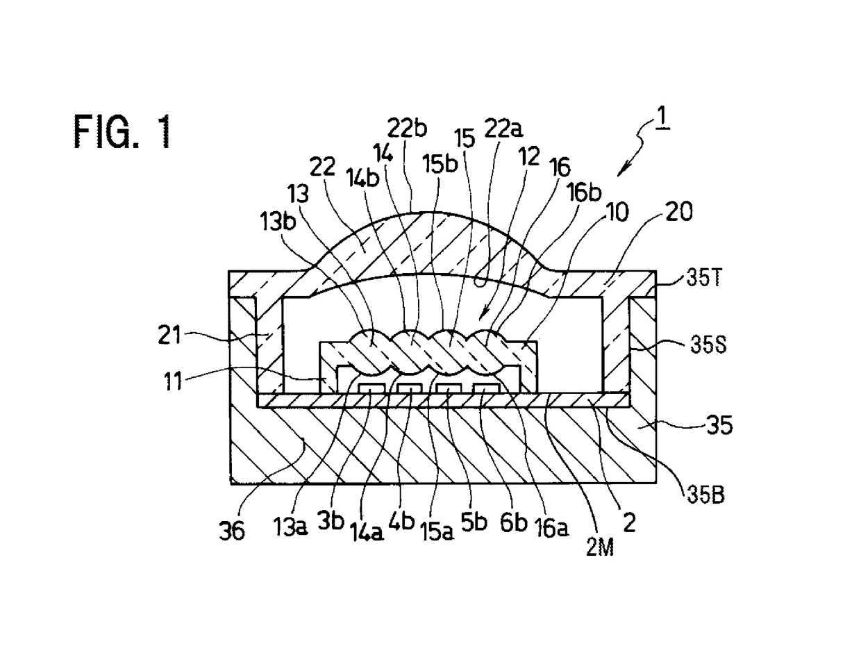
[0036]The disclosed subject matter will now be described in detail with reference to FIG. 1 to FIG. 13. FIG. 1 is a cross-sectional view showing an exemplary embodiment of a vehicular lamp made in accordance with principles of the disclosed subject matter. The vehicular lamp 1 can include: a casing 35 having a bottom surface 35B, a top surface 35T and a side surface 35S located between the top surface 35T and the bottom surface 35B made from a material having a high thermal conductivity such as a metallic plate, a ceramic material, etc.; a mounting board 2 having a mounting surface 2M located on the bottom surface 35B of the casing 35; and a plurality of light-emitting chips 3b, 4b, 5b and 6b located on the mounting surface 2M of the mounting board 2 as a matrix array, in which each of the light-emitting chips 3b, 4b, 5b and 6b includes a plurality of light-emitting chips extending in substantially parallel with respect to each other and also aligns in a direction substantially perp...


PUM


Abstract

A vehicular lamp including a drive assistance for drivers of forward vehicles can include a plurality of light-emitting chips located on a mounting board and arranged in a matrix array shape, a first optical lens and a second optical lens. When the light-emitting chips emit lights, the lights can form linear light distribution patterns including linear non-lighting-emitting zones between the adjacent linear light distribution patterns. Each of light-emitting times of the linear light distribution patterns and each of light-emitting cycles of the linear light distribution patterns can vary in accordance with a distance between a subject vehicle incorporating the vehicular lamp and the front vehicle, which moves in a forward direction of the subject matter. Therefore, the vehicular lamp with a simple structure can facilitate a driving safely when the drivers turn the forward vehicle around by confirming the linear light distribution patterns with a door / room mirror and a monitor.

Description

[0001]This application claims the priority benefit under 35 U.S.C. §119 of Japanese Patent Application No. 2015-207397 filed on Oct. 21, 2015, which is hereby incorporated in its entirety by reference.BACKGROUND[0002]1. Field[0003]The presently disclosed subject matter relates to vehicular lamps, and more particularly to vehicular lamps with a simple structure including a drive assistance for drivers of a forward vehicle, which moves in a frontward direction of a subject vehicle incorporating the vehicle lamp especially when the drivers turn the forward vehicle around, and thereby drivers of the subject vehicle may also be facilitated for a safe driving.[0004]2. Description of the Related Art[0005]When drivers turn a vehicle around while the drivers steer the vehicle, the vehicle is subject to a rear-end collision by a rearward vehicle, which approaches from a rearward direction of the vehicle, especially on a road with poor visibility at night. Hence, various drive assist apparatus...

Claims


Application Information

Patent Timeline
IPC IPC(8): F21S8/10B60Q1/04
CPCF21S48/1225F21S48/1388G06K9/00791F21S48/1208B60Q1/04F21S48/142F21S41/19F21S41/143F21S41/25F21S41/275F21S41/43F21S41/663F21S41/47F21S41/29F21S41/285F21S41/153G06V20/56
Inventor HIKI, SATORU
Owner STANLEY ELECTRIC CO LTD
Why Eureka
Eureka Blog
Learn More