
Method and system for optical fiber sensing

a technology of optical fiber and optical waveguide, applied in the field of optical fiber sensing, can solve the problems of not always convenient (or even necessary) to monitor

Active Publication Date: 2017-04-27
ARIEL SCI INNOVATIONS LTD
View PDF2 Cites 9 Cited by
  • Summary
  • Abstract
  • Description
  • Claims
  • Application Information

AI Technical Summary

Benefits of technology

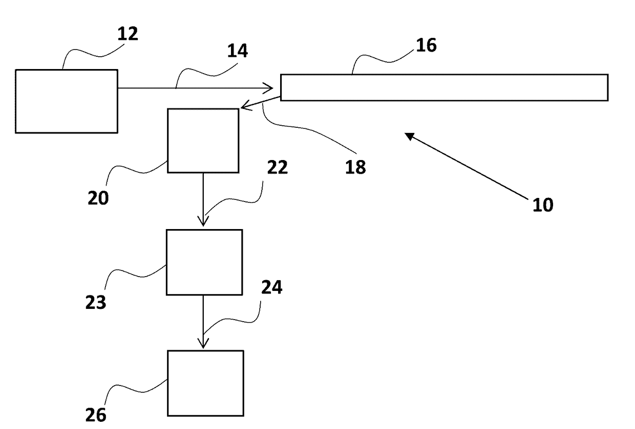
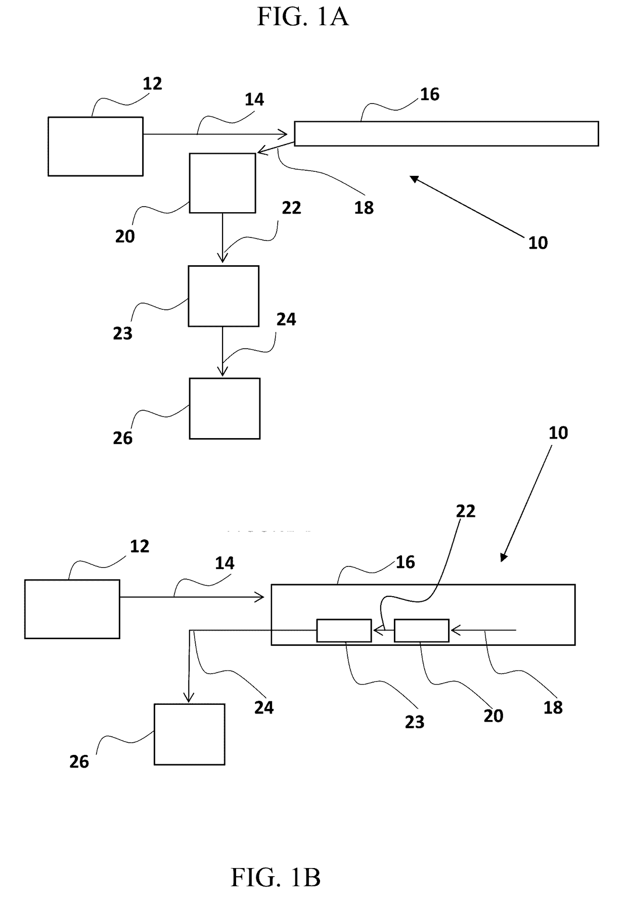
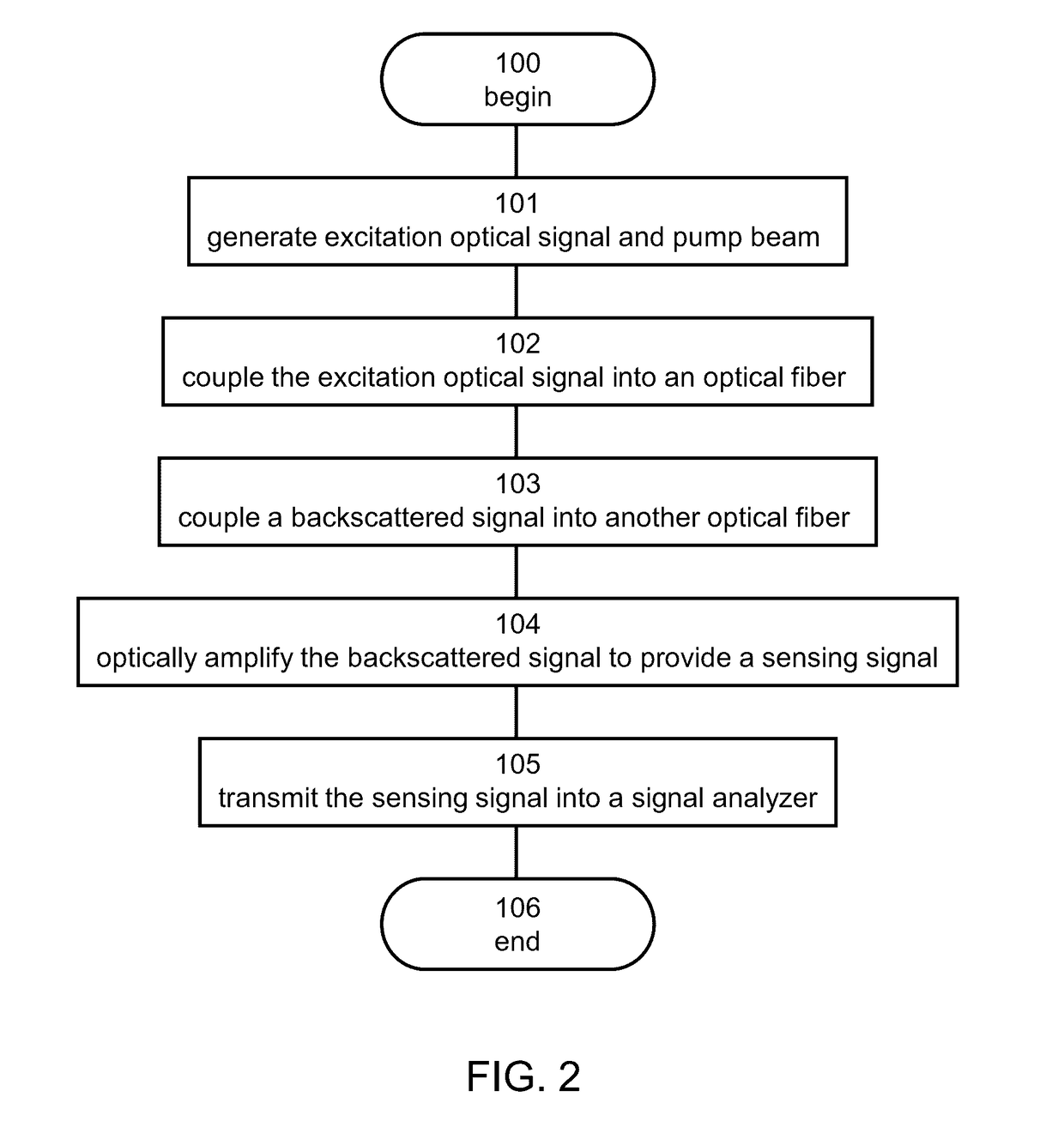
The present invention provides a method and system for optical sensing using Rayleigh backscattering. The method involves inducing a backscattered signal in a first optical fiber and optically amplifying it in a second optical fiber using a pump light beam. The optical amplification can be achieved by either Brillouin amplification or Raman amplification. The system includes a light source system, an optical coupler, and a signal analyzer. The method and system can be used for identifying changes in properties along the first fiber, such as strain, pressure, vibration, and chemical properties.

Problems solved by technology

However, it is not always convenient (or even necessary) to monitor the strain as it is occurring, and it is sufficient to know merely the maximum strain the structure has experienced in a given timeframe.

Method used


Image

  • Method and system for optical fiber sensing
  • Method and system for optical fiber sensing
  • Method and system for optical fiber sensing

Examples


examples

[0158]Reference is now made to the following examples, which together with the above descriptions illustrate some embodiments of the invention in a non limiting fashion.

[0159]The present example describes a technique referred to as Brillouin Amplification and signal processing of Rayleigh Scattering (BARS). As demonstrated below BARS is suitable for processing the information in a Rayleigh scattered signal. In the present example, two configurations for BARS are described internal BARS (iBARS), where Brillouin Amplification (BA) and Rayleigh scattering overlap in the same fiber and occur simultaneously, and external BARS (eBARS), where BA of the Rayleigh signal takes place in a different fiber.

[0160]An exemplified configuration of iBARS, according to some embodiments of the present invention is illustrated in FIG. 3. A CW laser is split into a first beam and a second beam. The first beam enters an optical fiber to act as a pump for BA within the fiber. The second beam is first downs...


PUM


Abstract

A method of optical sensing is disclosed. The method comprises coupling an excitation optical signal into a first optical fiber to induce Rayleigh backscattering, thereby providing a backscattered signal; coupling the backscattered signal into a second optical fiber, spatially separated from the first optical fiber; and optically amplifying the backscattered signal in the second optical fiber, thereby generating a sensing signal.

Description

RELATED APPLICATION[0001]This application claims the benefit of priority of U.S. Provisional Patent Application No. 62 / 012,429 filed Jun. 16, 2014, the contents of which are incorporated herein by reference in their entirety.FIELD AND BACKGROUND OF THE INVENTION[0002]The present invention, in some embodiments thereof, relates to optical fiber sensing and, more particularly, but not exclusively, to a method and system for sensing properties along an optical fiber.[0003]It is often desirable to monitor strain in a structure, such as a bridge or highway overpass, a building, or a component in a vehicle, in order to get advance warning of fracture or other failure of the structure. However, it is not always convenient (or even necessary) to monitor the strain as it is occurring, and it is sufficient to know merely the maximum strain the structure has experienced in a given timeframe. For example, for vehicles such as aircraft, weight, space and other limitations would preclude monitorin...

Claims


Application Information

Patent Timeline
IPC IPC(8): G01D5/353H01S3/30G01D5/36H01S3/067
CPCG01D5/35377H01S3/06754G01D5/36G01D5/35361H01S3/302G01M11/3109G01M11/319
Inventor STERNKLAR, SHMUELMERMELSTEIN, DAVID
Owner ARIEL SCI INNOVATIONS LTD
Learn More