Distributed Acoustic Sensing Systems and Methods Employing Under-Filled Multi-Mode Optical Fiber

Active Publication Date: 2016-11-24
HALLIBURTON ENERGY SERVICES INC
View PDF4 Cites 7 Cited by
  • Summary
  • Abstract
  • Description
  • Claims
  • Application Information

AI Technical Summary

Problems solved by technology

For example, recent distributed acoustic sensing system designs specify the use of single-mode optical fiber to achieve adequate sensing performance, yet many existing well installations employ multi-mode optical fiber, which would be largely infeasible to replace.

Method used


Image

  • Distributed Acoustic Sensing Systems and Methods Employing Under-Filled Multi-Mode Optical Fiber
  • Distributed Acoustic Sensing Systems and Methods Employing Under-Filled Multi-Mode Optical Fiber
  • Distributed Acoustic Sensing Systems and Methods Employing Under-Filled Multi-Mode Optical Fiber

Examples


Embodiment Construction

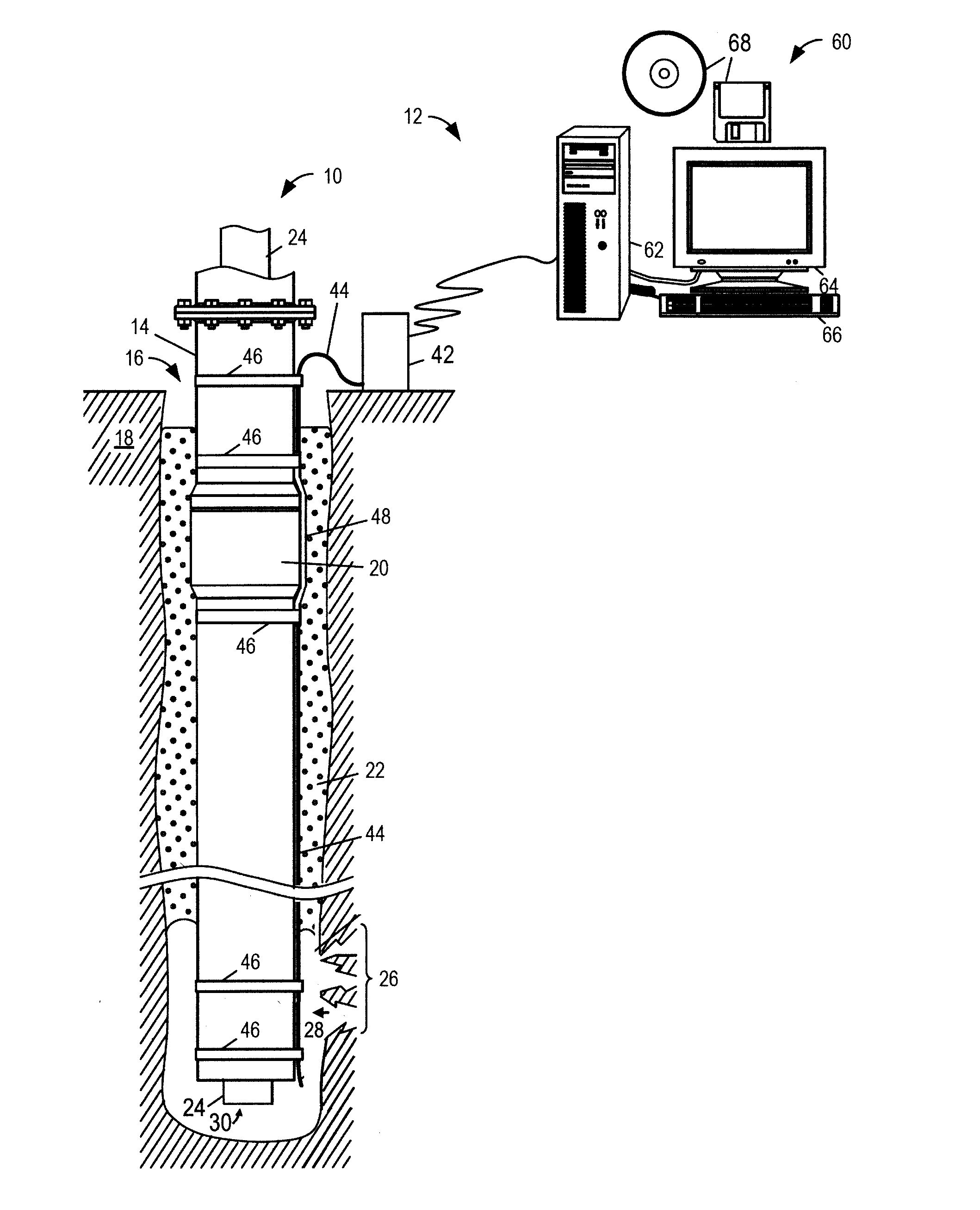
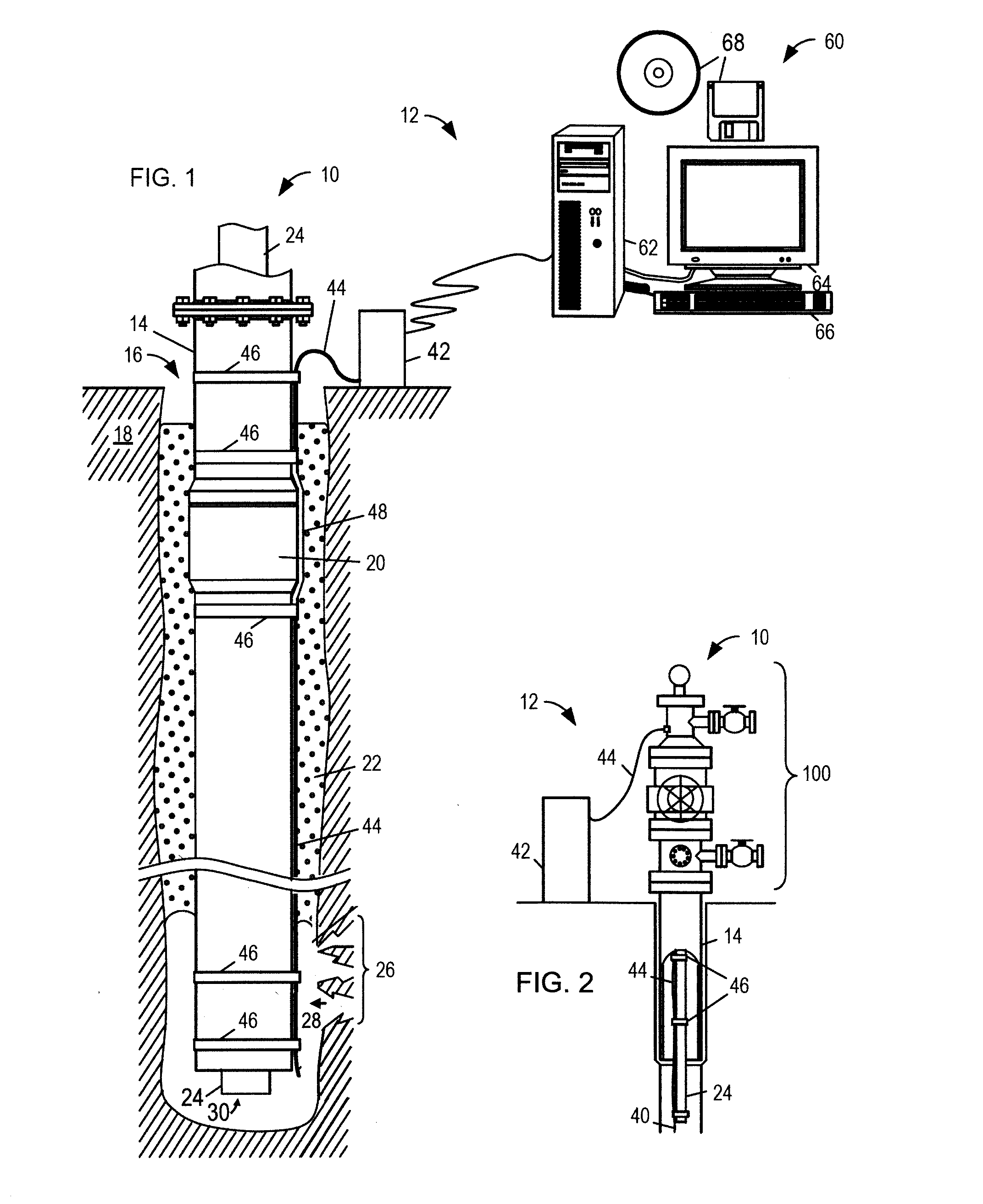
[0010]Certain disclosed system and method embodiments employ an under-filled multi-mode optical fiber for distributed interferometric phase sensing applications in the downhole environment. Many existing cable installations for distributed temperature sensing (“DTS”) in borehole environments and other asset monitoring applications employ graded index multi-mode fiber. The inventors have discovered that, contrary to accepted wisdom, many of the advantages provided by the use of a single-mode optical fiber for sensing (including coherency preservation and minimal dispersion) can also be achieved with multi-mode optical fiber for sensing, so long as the system employs an under-filled launch configuration to excite only the lowest-order modes in the multi-mode optical fiber.

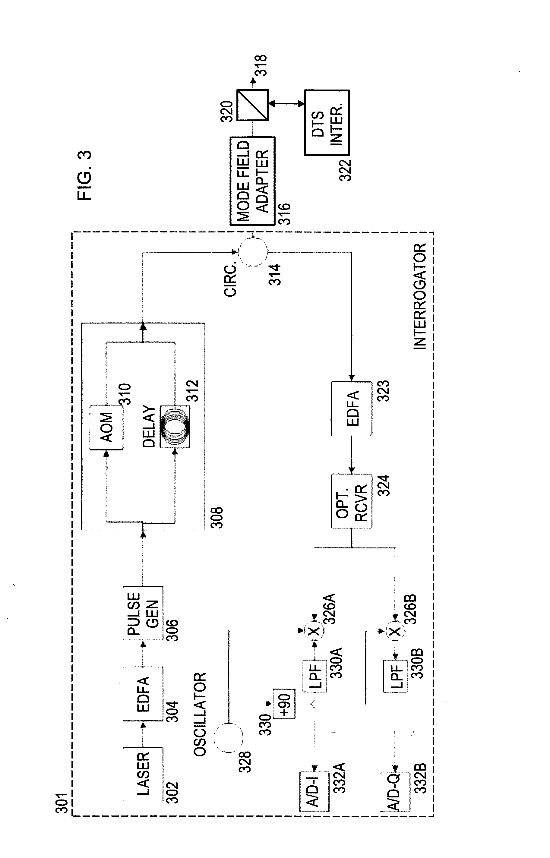
[0011]This approach further enables a single distributed sensing interrogator design for sensing with both single-mode and multi-mode optical fibers, without the extraordinarily high coupling losses that would genera...


PUM


Abstract

An illustrative distributed acoustic sensing system includes a multi-mode optical fiber cable for distributed sensing and a distributed acoustic sensing interrogator coupled to the multi-mode optical fiber cable via a single mode optical fiber. The interrogator derives distributed acoustic measurements from Rayleigh backscattering light that is initiated with a substantially under-filled launch configuration that is designed to excite only the lowest-order modes of the multi-mode optical fiber. Mode conversion within the multi-mode optical fiber is anticipated to be negligible. For elastic scattering (i.e., Rayleigh scattering), it is further anticipated that the scattered light will be primarily returned in the incident propagation mode, thereby escaping the extraordinarily large coupling loss that would otherwise be expected from coupling a single-mode optical fiber to a multi-mode optical fiber for distributed sensing. Experiments with graded index multi-mode optical fiber have yielded positive results.

Description

CROSS-REFERENCE TO RELATED APPLICATIONS[0001]The present application is a continuation of U.S. patent application Ser. No. 14 / 068,448, titled “Distributed Acoustic Sensing Systems and Methods Employing Under-Filled Multi-Mode Optical Fiber” and filed on Oct. 31, 2013 by David A. Barfoot and John L. Maida. The foregoing application is hereby incorporated herein in their entirety.BACKGROUND[0002]Distributed optical sensing technology is turning out to be suitable for a number of downhole applications ranging from temperature sensing to passive seismic monitoring. As engineers develop new and improved systems to increase performance and sensitivity, they have encountered certain obstacles. For example, recent distributed acoustic sensing system designs specify the use of single-mode optical fiber to achieve adequate sensing performance, yet many existing well installations employ multi-mode optical fiber, which would be largely infeasible to replace. The inventors are unaware of any ex...

Claims


Application Information

Patent Timeline
Patent Type & Authority Applications(United States)
IPC IPC(8): G01V1/40G01H9/00G01V1/22
CPCG01V1/40G01H9/004G01V1/226
Inventor BARFOOT, DAVID A.MAIDA, JOHN L.
Owner HALLIBURTON ENERGY SERVICES INC
Why Eureka
Try Eureka