Optical device

Active Publication Date: 2012-12-27
SUMITOMO ELECTRIC IND LTD
View PDF4 Cites 20 Cited by
  • Summary
  • Abstract
  • Description
  • Claims
  • Application Information

AI Technical Summary

Benefits of technology

[0024]According to the present invention, coupling l

Problems solved by technology

In this case, angular adjustment and alignment between the multi-core fiber and the single core fibers are so difficult, which

Method used


Image

  • Optical device
  • Optical device
  • Optical device

Examples


first embodiment

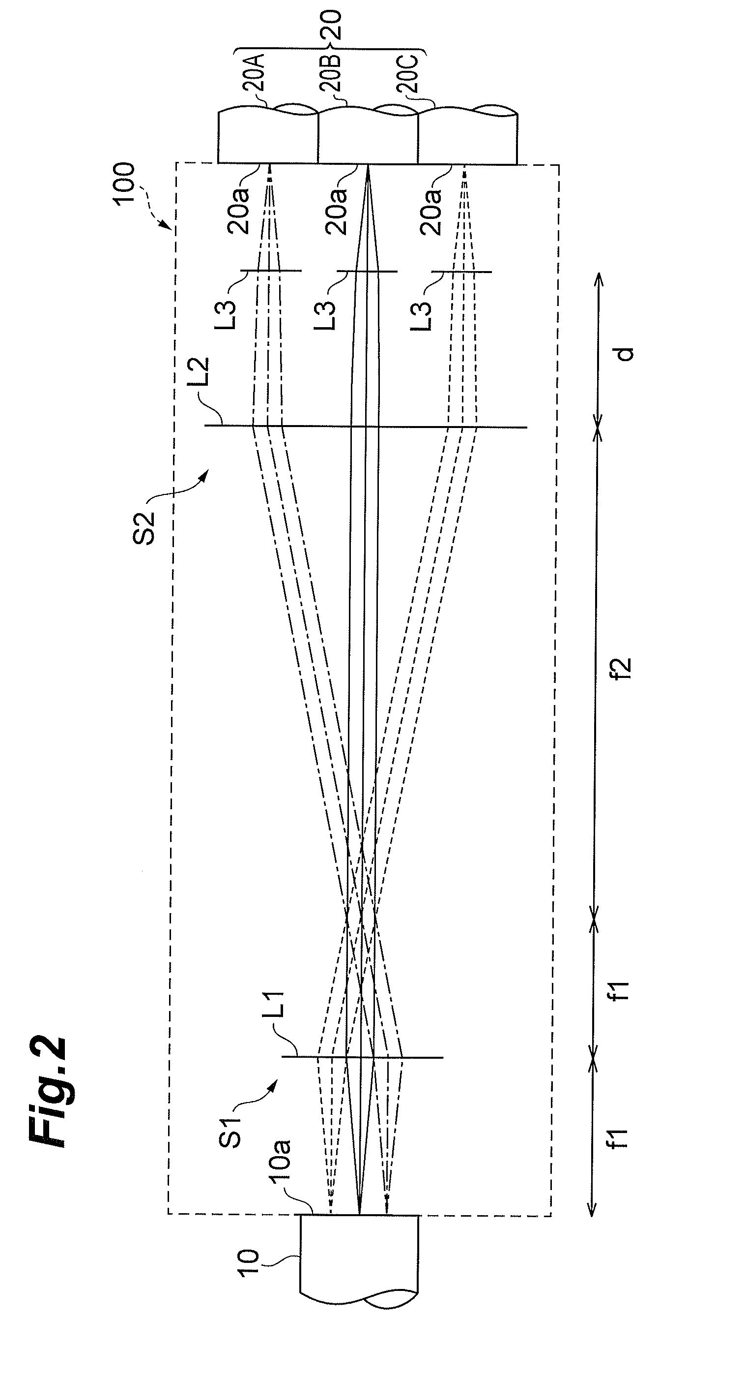
[0047]First, an optical device 100 according to the first embodiment will be described with reference to FIG. 2.

[0048]As shown in FIG. 2, the optical device 100 is a device for coupling the multi-core fiber 10 (optical element) to the single core fibers 20 (other optical components) in order to propagate a single-mode light signal (wavelength multiplexed signal), and is configured by including a first optical system S1 and a second optical system S2. Hereinafter, the optical device using the multi-core fiber as an optical element and being included in the present invention is referred to as multi-core fiber coupling device.

[0049]The multi-core fiber 10 used in this embodiment is an optical element including a plurality of light output parts having respective optical axes that are parallel to one another, and specifically, has seven core regions, and emits seven beams (only three beams are shown in a sectional view of FIG. 2) from an emitting end surface 10a. More specifically, the s...

second embodiment

[0061]Subsequently, a multi-core fiber coupling device 100A according to the second embodiment will be described with reference to FIG. 4.

[0062]As shown in FIG. 4, the multi-core fiber coupling device 100A is different from the multi-core fiber coupling device 100 according to the first embodiment only in a configuration of the second optical system S2.

[0063]The second optical system S2 of the multi-core fiber coupling device 100A are constituted by a lens array L4 to L6. The lens array is constituted by seven lenses (only the three lenses L4 to L6 are shown in a sectional view of FIG. 4) so as to correspond to the respective seven beams. A focal length of each of the seven lenses L4 to L6 of the second optical system S2 is f1, which is equal to the focal length of the condensing lens L1 of the first optical system S1.

[0064]For this reason, the spread angle θOUT on the end surface 10a of the multi-core fiber 10 becomes equal to the spread angle θIN on the end surfaces of the single ...

third embodiment

[0067]Next, a multi-core fiber coupling device 100B according to the third embodiment will be described with reference to FIG. 6 to FIG. 8.

[0068]As shown in FIG. 6, the multi-core fiber coupling device 100B is different from the multi-core fiber coupling device 100A according to the second embodiment described above only in a configuration of the second optical system S2. That is, the second optical system S2 of the multi-core fiber coupling device 100B is constituted by one lens array in which seven lens pieces L7 to L9 are combined in place of the seven lenses L4 to L6.

[0069]Such multi-core fiber coupling device 100B also can obtain the same or similar effect as the multi-core fiber coupling device 100 according to the first embodiment.

[0070]Here, in the case of more practical lens, not an ideal lens, an aberration of the lens is required to be considered.

[0071]As shown in FIG. 7, a plurality of beams passing through the lens array L7 to L9 of the second optical system S2 does not...


PUM


Abstract

An optical device which reduces coupling loss while improving practicality is provided. A multi-core fiber coupling device is an optical device which couples a multi-core fiber to single core fibers, and includes a first optical system which is located on optical axes of a plurality of beams emitted from the multi-core fiber, and which makes the optical axes of the respective beams non-parallel to each other, thereby making the beams in a state of being separated from each other, and a second optical system S2 which makes the optical axes of the plurality of beams in a state of being non-parallel to each other on the side of the first optical system, in a state of being approximately parallel to each other.

Description

BACKGROUND OF THE INVENTION[0001]1. Field of the Invention[0002]The present invention relates to an optical device for coupling an optical component such as a plurality of single core fiber, to an optical element such as a multi-core fiber.[0003]2. Related Background of the Invention[0004]Conventionally, a multi-core fiber coupling device for coupling a plurality of single core fibers to a multi-core fiber is known. For example, Japanese unexamined Patent Publication No. 60-212710 discloses a device in which a lens is interposed between a multi-core fiber having two core regions and two single core fibers in order to branch the multi-core fiber. The lens in this device deflects a plurality of beams emitted from the multi-core fiber so as to be separated from each other in a direction inclined relative to an optical axis of the multi-core fiber.[0005]According to the above-mentioned conventional art, since the lens inclines the beams from the multi-core fiber, in accordance with the ...

Claims


Application Information

Patent Timeline
IPC IPC(8): G02B6/26G02B6/35G02B6/32
CPCG02B6/32G02B27/0955G02B6/29311G02B6/356G02B6/3512
Inventor INOUE, AKIRATAKAHASHI, KENICHIROKANIE, TOMOHIKOHARUMOTO, MICHIKO
Owner SUMITOMO ELECTRIC IND LTD
Why Eureka
Try Eureka