Laser projection illumination system

Active Publication Date: 2017-04-27
BARCO NV
View PDF7 Cites 15 Cited by
  • Summary
  • Abstract
  • Description
  • Claims
  • Application Information

AI Technical Summary

Benefits of technology

[0040]In an embodiment, the method of projecting light beams according to the present invention further comprises changing the direction of one or several individ

Problems solved by technology

Further, a large spread of the angular and spatial distribution between the primary colors will reduce the efficiency of any use of diffusive-based de-speckling techniques later in the system.
However there are undesirable light losses associated with the fiber coupling technique.
Further, fiber based so

Method used


Image

  • Laser projection illumination system
  • Laser projection illumination system
  • Laser projection illumination system

Examples


Embodiment Construction

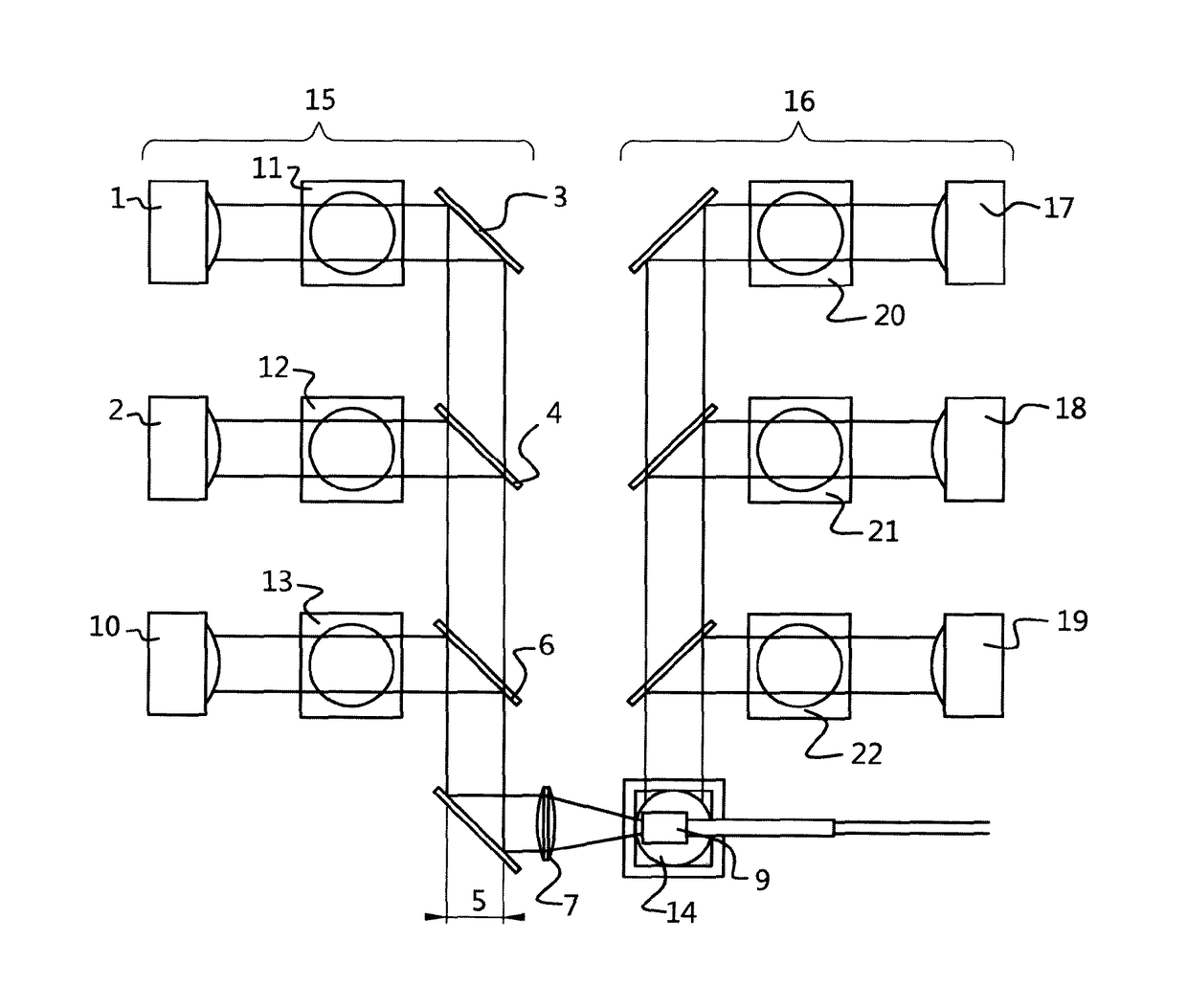
[0056]FIG. 1 shows an example of an embodiment of the present invention with two cluster beams 1 and 2 and dichroic mirrors 3 and 4 to alter the direction of the light beams. The three-dimensional nature of light beams makes the number of visible beams in a two dimensional snapshot like FIG. 1 to depend on the beam distribution and the angle of the two-dimensional view. The etendue of an individual beam of cluster 1 may be different than the etendue of an individual beam of set 2. It is however crucial that the etendues of the cluster beams 1 and 2 are equal as well as the etendue of the final beam leaving mirror 4. The two-dimensional projection of this etendue is indicated in FIG. 1 by 5.

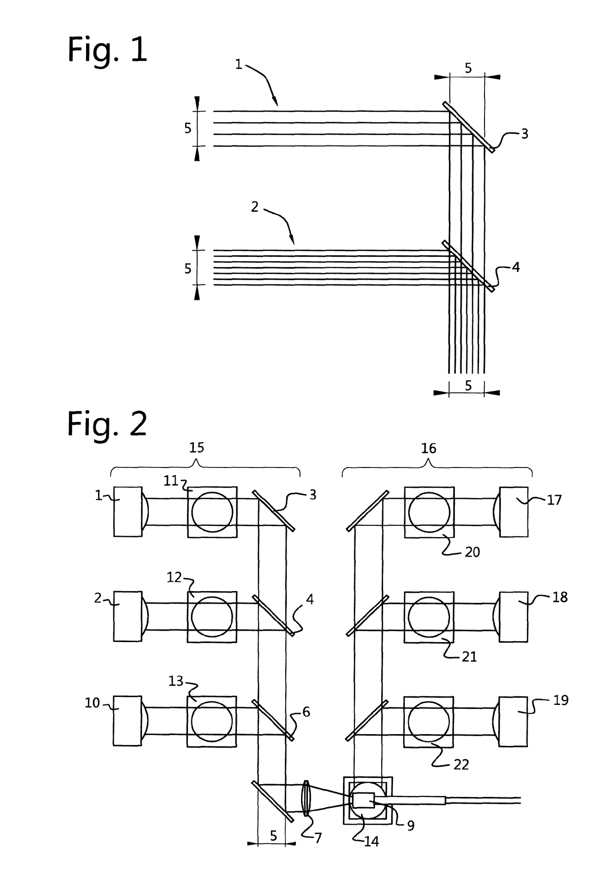
[0057]FIG. 2 shows an overview of an embodiment of the present invention.

[0058]Light beams 1 and 2 are here presented in a system configuration where 1 and 2 could for example be blue and green light. A third light beam 10 is added; this could for example be red light. 1, 2 and 10 contribute to th...


PUM


Abstract

A light beam projecting arrangement including a first cluster of light sources arranged to provide a first cluster of light beams having a first etendue and a second cluster of light sources arranged to provide a second cluster of light beams having a second etendue, and means for changing the direction of the first cluster and/or the second cluster of light beams. The light sources are arranged so that the total etendue of the first cluster of light beams is substantially equal to the etendue of the second cluster of light beams; and where the means for changing the direction are arranged so that the clusters of light beams are brought into a combined cluster light beam having substantially the same etendue as the larger one of the first etendue and the second etendue.

Description

FIELD OF THE INVENTION[0001]The present invention relates to a projection illumination system and to a method of operating or manufacturing a projection illumination system.BACKGROUND[0002]Laser based projection systems are considered to be a promising technology for (high-end) projection due to their high lifetime, saturated colors, stable light output, etc. Two focus areas in this field are how to increase the efficiency and how to deal with the speckle phenomenon. For example, international patent application publication WO2012 / 139634 A1, in the name of the present applicant, describes how to decrease the impact of the speckle behaviour by using an increased diffusing power.[0003]Laser based projection systems involve distinct red, green and blue light sources that can provide primary light beams or primary colors. A primary cluster light beam can comprise a plurality of individual light beams. There is an angular and spatial distribution associated with a cluster light beam. The...

Claims


Application Information

Patent Timeline
IPC IPC(8): G03B33/12G02B27/48G03B21/20
CPCG03B33/12G03B21/2033G03B21/2013G02B27/48G03B21/208G03B21/2073G03B21/2066G02B27/0905G02B27/0922G02B27/14H04N9/3161G02B27/283
Inventor D'OOSTERLINCK, WOUTERJANSSENS, PETERCOULIER, NICO
Owner BARCO NV
Why Eureka
Try Eureka