
X-ray ct device and processing device

Active Publication Date: 2017-05-04
FUJIFILM HEALTHCARE CORP
View PDF2 Cites 6 Cited by
  • Summary
  • Abstract
  • Description
  • Claims
  • Application Information

AI Technical Summary

Benefits of technology

The invention allows for the determination of parameters for reconstructing an image using iterative methods. This is done without being affected by factors like the type of machine or configuration being used. The technical effect of this is that it allows for a more consistent and accurate image to be created regardless of external factors.

Problems solved by technology

Satisfying the condition for high image quality necessary for diagnosis of the physician inevitably involves the subject in radiation exposure to a certain degree.
As a result, linear streak artifact and granular noise which may cause diagnostic error may increasingly occur.

Method used


Image

  • X-ray ct device and processing device
  • X-ray ct device and processing device
  • X-ray ct device and processing device

Examples


first embodiment

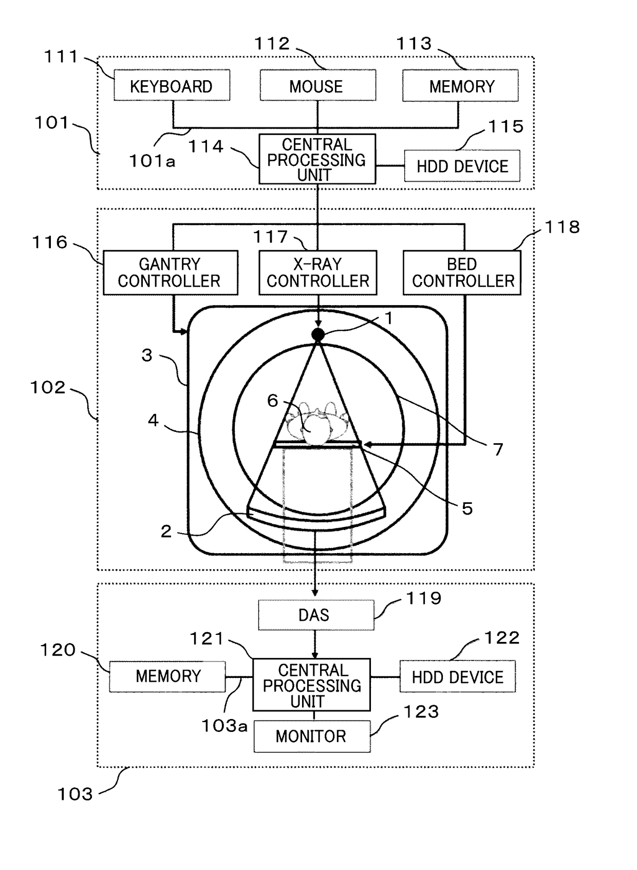
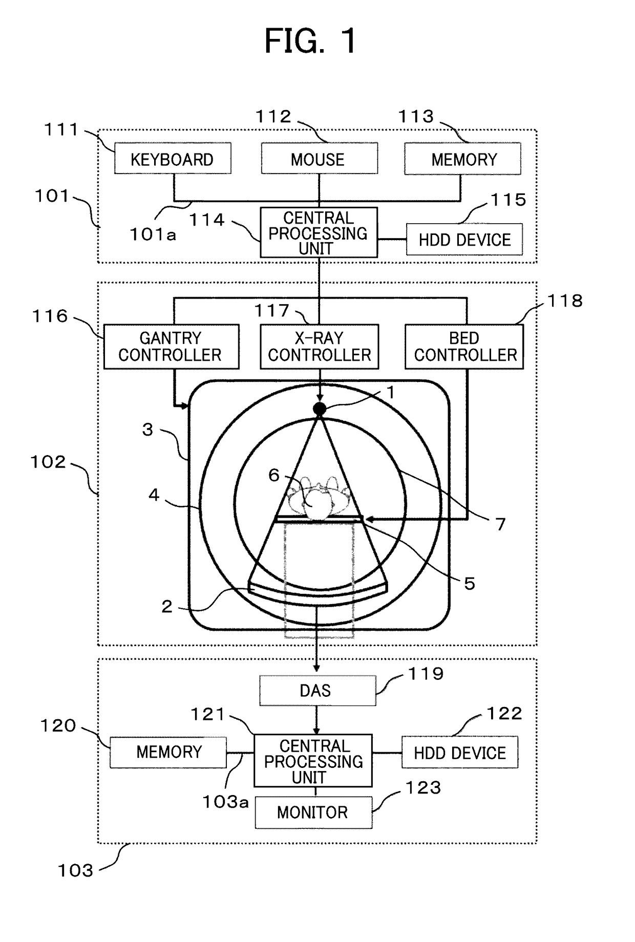
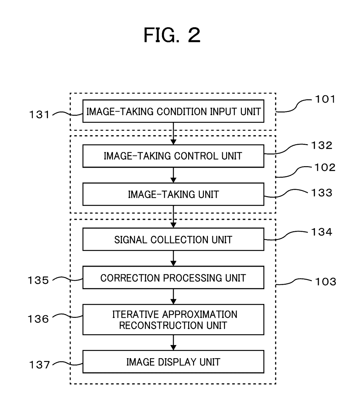
[0049]FIG. 1 is a view showing a hardware structure of an X-ray CT device according to a first embodiment. FIG. 2 is a functional block diagram showing functions of the X-ray CT device according to the first embodiment. The X-ray CT device according to the embodiment includes an image-taking section 102 and an image generation section 103. The image-taking section 102 includes an X-ray generation unit 1 for generating X-ray, an X-ray detection unit 2 for detecting the X-ray after transmitting through the subject to acquire measured projection data, and a mechanism having the X-ray generation unit and the X-ray detection unit installed, which rotates around the subject. The image generation section 103 includes an iterative reconstruction unit 136 that generates the CT image based on the measured projection data from the image-taking section, and iteratively corrects the CT image so as to equalize the difference between the calculated projection data obtained by a forward projection ...

second embodiment

[0121]The X-ray CT device according to the second embodiment will be described.

[0122]The first embodiment is configured to calculate the parameter β image βI(j) by using the reference parameter βb, reference weight Wb, and the weight image WI(j) at each position for setting the weight set as the constant value in the weight set region 144. For setting the photon number of the detection element by the weight set region 144, the second embodiment is configured to calculate the parameter β image βI(j) by using the reference parameter βb calculated with the weight set as the constant value, the reference weight Wb, and the weight image WI(j) at each position calculated with the photon number of the detection element. The structure of the X-ray CT device according to the second embodiment will be described while focusing on the structure different from that of the X-ray CT device according to the first embodiment.

[0123]FIG. 11 shows the weight images WI(j) calculated from the result of t...

third embodiment

[0128]The X-ray CT device according to the third embodiment will be described. The first embodiment is configured to calculate the parameter β image βI(j) by using the reference weight Wb at the rotation center set at the reference position, the reference parameter βb, and the weight image WI(j) at each of the respective positions for setting the weight set as the constant value in the weight set region 144. The third embodiment is configured to calculate the parameter β image βI(j) by using a plurality of reference weights Wb in addition to the rotation center, a plurality of reference parameters βb, and the weight images WI(j) at the respective positions. The structure of the X-ray CT device according to the third embodiment will be described while focusing on the structure different from that of the X-ray CT device according to the first embodiment.

[0129]The left side of FIG. 14 shows a plurality of ROIs 191 set on the CT image iteratively corrected by using the respective refere...


PUM


Abstract

This X-ray CT device uses iterative reconstruction to obtain a CT image with the desired noise reduction or X-ray reduction ratio. An iterative approximation reconstruction unit (136) is provided which, from measured projection data obtained by an X-ray detection unit of the X-ray CT device, iteratively reconstructs a CT image in a reconstruction range of a subject, and iteratively corrects the CT image such that calculated projection data, calculated through forward projection of a CT image, is the same as the difference between measured projection data detected by the X-raw detection unit and calculated projection data. The iterative approximation reconstruction unit is provided with a parameter determination unit (151), an iterative correction unit (152), and a table unit (153) which calculates in advance the relation between each parameter used in the iterative reconstruction, and noise reduction or X-ray reduction ratio in the CT image. The parameter determination unit (151) determines the parameters from a calculation table in the table unit (153) depending on the desired reduction ratio.

Description

TECHNICAL FIELD[0001]The present invention relates to an X-ray CT (Computed Tomography) device, and more particularly, to an iterative reconstruction technology for iteratively correcting the CT image.BACKGROUND ART[0002]The X-ray CT device is configured to calculate an X-ray absorption coefficient at each point in a subject body from measured projection data obtained by multidirectionally taking images of the subject, and acquire the X-ray absorption coefficient distribution image (hereinafter referred to as CT image). Generally, the X-ray absorption coefficient is replaced with a CT value standardized with air and water (air: −1000, water: 0) for diagnostic use.[0003]The CT image is expressed by superposing tomographic planes of the subject along the body axis. The CT image is clinically useful in the medical site because the use of the CT image allows correct and instantaneous diagnosis of the patient condition. Satisfying the condition for high image quality necessary for diagno...

Claims


Application Information

Patent Timeline
IPC IPC(8): A61B6/00A61B6/03
CPCA61B6/5258A61B6/032A61B6/467A61B6/461A61B6/5205G06T11/006G06T2211/424
Inventor YAMAKAWA, KEISUKEKOJIMA, SHINICHI
Owner FUJIFILM HEALTHCARE CORP
Learn More