Tof camera system and a method for measuring a distance with the system

a camera system and distance measurement technology, applied in the field of tof camera system and distance measurement method with the system, can solve the problems of high cost and low resolution obtained

Active Publication Date: 2017-05-04
SONY DEPTHSENSING SOLUTIONS SA NV
View PDF8 Cites 26 Cited by
  • Summary
  • Abstract
  • Description
  • Claims
  • Application Information

AI Technical Summary

Benefits of technology

[0011]processing the said corresponding data for eliminating the influence of the indirect light beams in the depth map of the object.
[0012]Advantageously, when processing the data, the method could comprise a step of identifying, for instance on an intermediary depth ...

Problems solved by technology

For instance, multiple frequency approaches have been performed, by acquiring a set of depth measurements with different ...

Method used


Image

  • Tof camera system and a method for measuring a distance with the system
  • Tof camera system and a method for measuring a distance with the system
  • Tof camera system and a method for measuring a distance with the system

Examples


Embodiment Construction

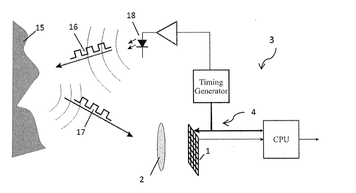
[0029]FIG. 3 illustrates a TOF camera system 10 according to an embodiment of the invention. The Time-Of-Flight camera system 10 comprises an illumination unit 20 for illuminating a scene 24 with a modulated light. The light emitted by this illumination unit 20 is arranged for being suitable for measuring distances using the Time-Of-Flight technology. For instance, the illumination unit 20 may be arranged for emitting light pulses with an appropriate pulse width. Indeed, when using pulses, the pulse width of each light pulse determines the camera range. For instance, for a pulse width of 50 ns, the range is limited to 7.5 m. As a consequence, the illumination of the scene becomes critical to the operation of a TOF camera system, and the high speed driving frequency requirements for illumination units necessitate the use of specialised light sources such as light emitting diodes (LEDs) or lasers to generate such short light pulses. The illumination unit is arranged for emitting multi...


PUM


Abstract

The invention relates to a method for measuring a distance between an object of a scene and a Time-Of-Flight camera system, and providing a depth map of the object, the Time-Of-Flight camera system comprising an illumination unit, an imaging sensor having a matrix of pixels and image processing means, the method being characterized by the following steps: modifying in a discrete way the illumination of said illumination unit in order to illuminate elementary areas of the scene with different incident intensities, respectively, for distinguishing the direct incident light beams from the indirect incident light beams; receiving onto the pixels of the matrix of the sensor the beams reflected by said elementary areas and providing the image processing means with corresponding data; processing the said corresponding data for eliminating the influence of the indirect light beams in the depth map of the object.

Description

TECHNICAL FIELD OF THE INVENTION[0001]The invention relates (i) to a method for measuring a distance between an object of a scene and a Time-Of-Flight camera system and (ii) to the Time-Of-Flight camera system associated therewith. In particular, the invention relates to the problem of direct and indirect reflections of light within a scene and to the errors of depth measurements induced by these multiple reflections. It should be understood that by scene is meant all the surfaces surrounding the object onto which a light beam could be directly or indirectly reflected.BACKGROUND OF THE INVENTION[0002]Time-Of-Flight technology (TOF) is a promising technology for depth perception. The well-known basic operational principle of a standard TOF camera system 3 is illustrated in FIG. 1. The TOF camera system 3 captures 3D images of a scene 15 by analysing the time of flight of light from a dedicated illumination unit 18 to an object. TOF camera system 3 includes a camera, for instance a ma...

Claims


Application Information

Patent Timeline
IPC IPC(8): G01S17/89G01S7/487G01S17/10G01S7/4911G01S17/894
CPCG01S17/89G01S7/4876G01S17/10G01S7/4911G01S7/493G01S17/46G01S17/894
Inventor VAN DER TEMPEL, WARD
Owner SONY DEPTHSENSING SOLUTIONS SA NV
Why Eureka
Try Eureka