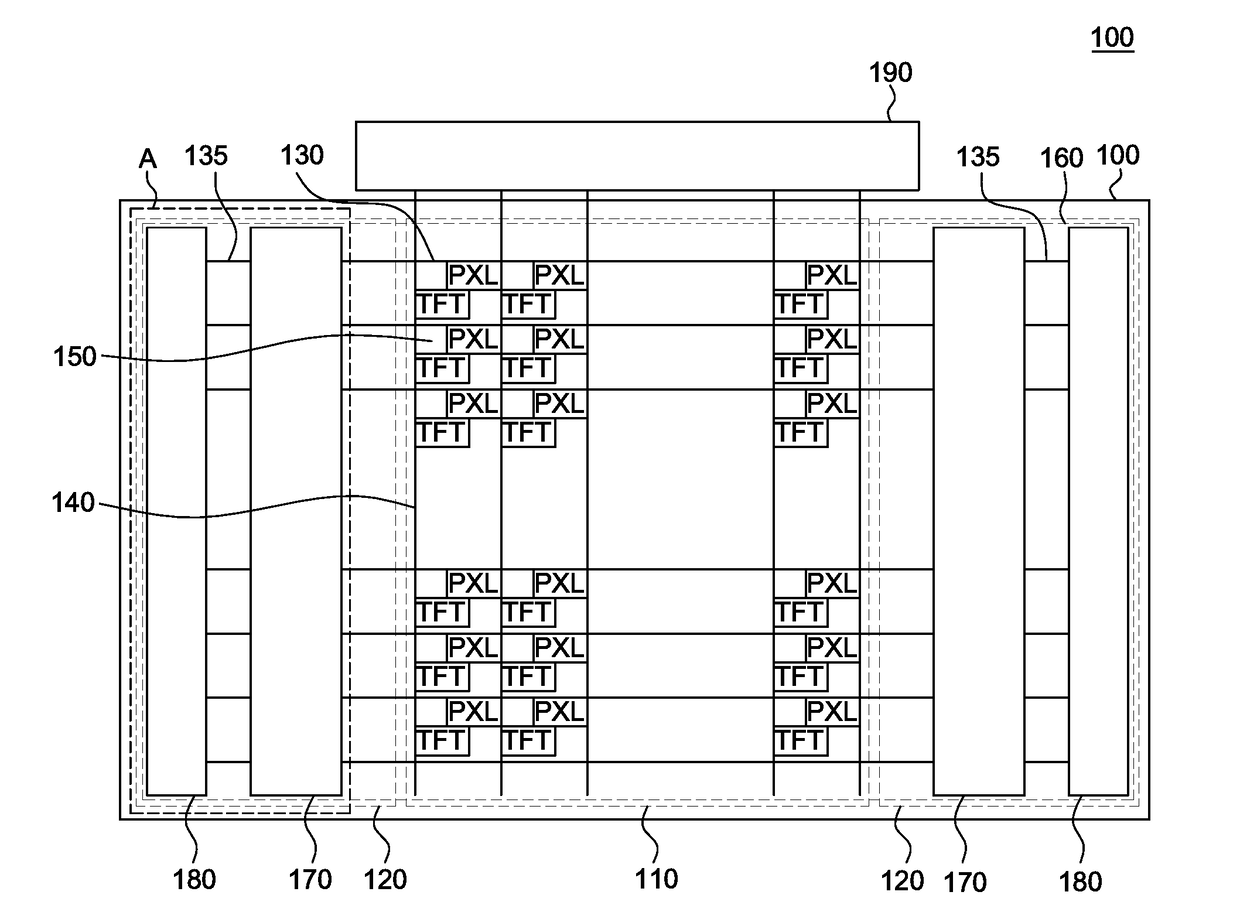
Array substrate

a technology of array substrate and array substrate, which is applied in the field of array substrate, can solve the problems of affecting the lifespan of the gip circuit and the size of the buffer, the effect of reducing the width of the non-display area, and suppressing the delay of signals

Active Publication Date: 2017-05-04
LG DISPLAY CO LTD
View PDF7 Cites 15 Cited by
  • Summary
  • Abstract
  • Description
  • Claims
  • Application Information

AI Technical Summary

Benefits of technology

[0018]In view of the above problems recognized by the present inventors, an object of the present disclosure is to provide an array substrate for a display device, which is capable of suppressing delay in signals due to increase in load on clock signal lines inputting signal to a GIP circuit and implementing a narrow bezel by reducing the width of a non-display area on the left and right sides of a display area.

Problems solved by technology

Such IPS-LCD devices have the advantage of wide viewing angle but have the drawback of low aperture ratio and low transmittance.
If the delay in the signals increases with the load on the clock signal lines, the lifespan of the GIP circuit and the size of a buffer, i.e., a transistor included in the GIP circuit may be affected.
In this manner, however, the size of the bezel undesirably increases.
Further, overlap capacitance between the clock signal lines and between clock signal lines and connection lines connecting the clock signal lines to the GIP circuit is undesirably increased.
Therefore, RC delay may not be sufficiently reduced at the cost of increased bezel.
Moreover, as the size of the bezel should be reduced in order to implement LCD devices with a more narrow bezel, the space allowed for clock signal lines becomes smaller, and thus RC delay in the clock signal lines undesirably increases.

Method used


Image

  • Array substrate
  • Array substrate
  • Array substrate

Examples


Embodiment Construction

[0036]Advantages and features of the present disclosure and methods to achieve them will become apparent from the descriptions of exemplary embodiments hereinbelow with reference to the accompanying drawings. However, the present disclosure is not limited to exemplary embodiments disclosed herein but may be implemented in various different ways. The exemplary embodiments are provided for making the disclosure of the present invention thorough and for fully conveying the scope of the present invention to those skilled in the art. It is to be noted that the scope of the present disclosure is defined only by the claims.

[0037]The figures, dimensions, ratios, angles, the numbers of elements given in the drawings are merely illustrative and are not limiting Like reference numerals denote like elements throughout the descriptions. Further, in describing the present disclosure, descriptions on well-known technologies may be omitted in order not to unnecessarily obscure the gist of the prese...


PUM


Abstract

An array substrate includes: a display area; a non-display area outside of the display area; a gate-in-panel (GIP) circuit in the non-display area; a plurality of clock signal lines in the non-display area and configured to transfer signals to the GIP circuit; and connection lines in the non-display area and configured to connect the plurality of clock signal lines to the GIP circuit. Each of the plurality of clock signal lines is a ring shaped line.

Description

CROSS-REFERENCE TO RELATED APPLICATIONS[0001]This application claims the priority of Korean Patent Application No. 10-2015-0152594 filed on Oct. 30, 2015, in the Korean Intellectual Property Office, the disclosure of which is incorporated herein by reference in its entirety for all purposes as if fully set forth herein.BACKGROUND[0002]Technical Field[0003]The present disclosure relates to a display device having an array substrate and a method of manufacturing the same, and more specifically to an array substrate capable of reducing signal delay in clock signal lines and reducing the size of a bezel in a non-display area.[0004]Description of the Related Art[0005]As the era of information technology has begun, the field of display that represents electrical information signals graphically has been rapidly growing. In accordance with this, various display devices which are thinner, lighter and consume less power have been developed.[0006]Examples of such display devices include a liqu...

Claims


Application Information

Patent Timeline
Patent Type & Authority Applications(United States)
IPC IPC(8): G09G3/36
CPCG09G3/3648G09G2320/0223G09G2300/0465G09G2320/0209G09G2300/0426G09G2310/0286G09G3/3659G11C19/28G09G3/3677G09G2300/0408G09G2300/0434
Inventor KIM, BYOUNGWOOYU, SANGHEE
Owner LG DISPLAY CO LTD
Why Eureka
Try Eureka