Flex-rigid wiring board and electronic device

A technology for flexible circuit boards and electronic equipment, applied in printed circuits, printed circuits, printed circuit manufacturing, etc., can solve problems such as the size limitation of rigid substrates, achieve the effect of shortening signal paths and suppressing signal delays

Inactive Publication Date: 2013-05-08
IBIDEN CO LTD
View PDF0 Cites 0 Cited by
  • Summary
  • Abstract
  • Description
  • Claims
  • Application Information

AI Technical Summary

Problems solved by technology

Therefore, even if the width of the flexible substrate is to be enlarged, it is limited by the size of the rigid substrate.

Method used


Image

  • Flex-rigid wiring board and electronic device
  • Flex-rigid wiring board and electronic device
  • Flex-rigid wiring board and electronic device

Examples


Embodiment Construction

[0075] Next, a flex-rigid circuit board and an electronic device according to an embodiment of the present invention will be described.

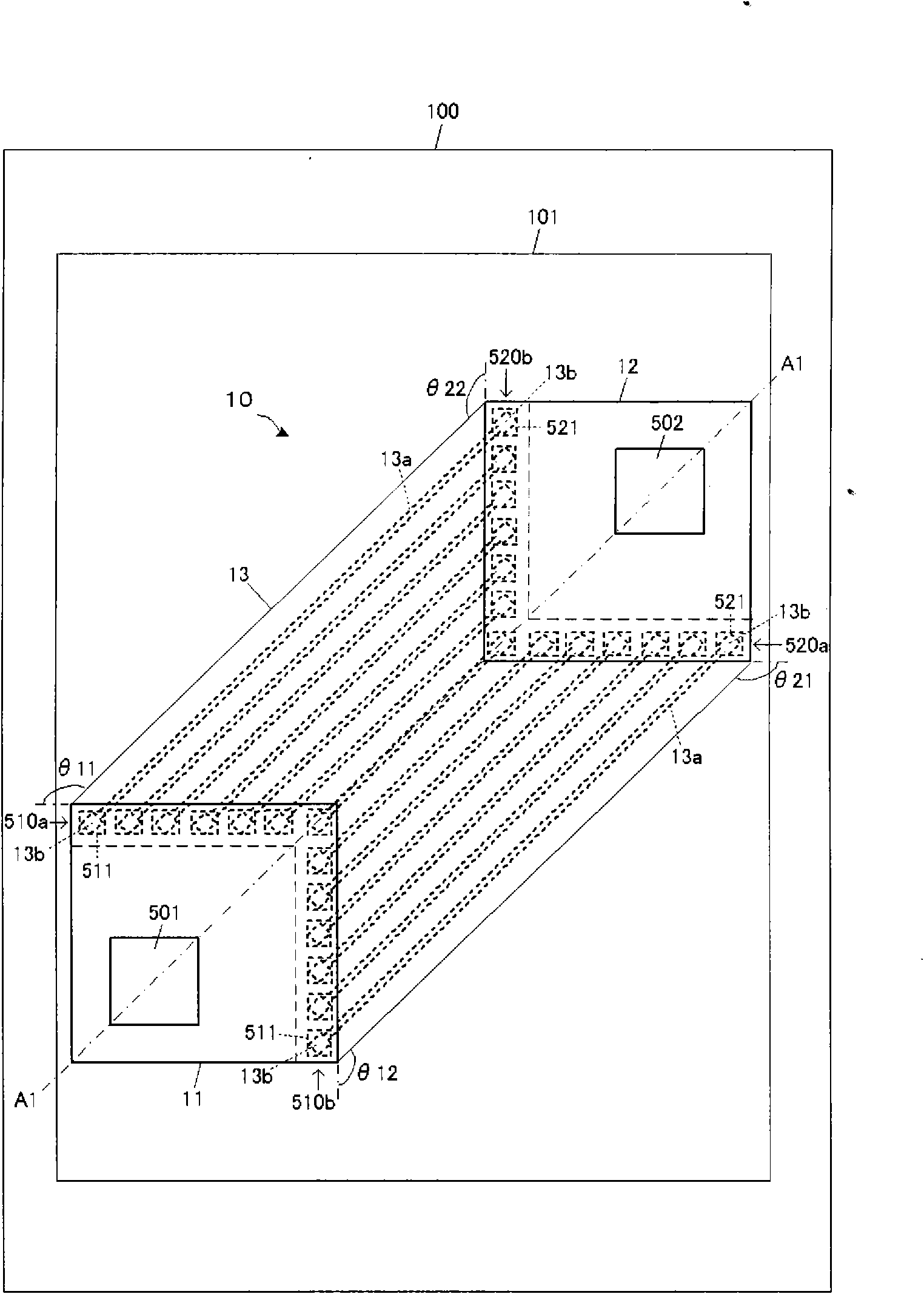
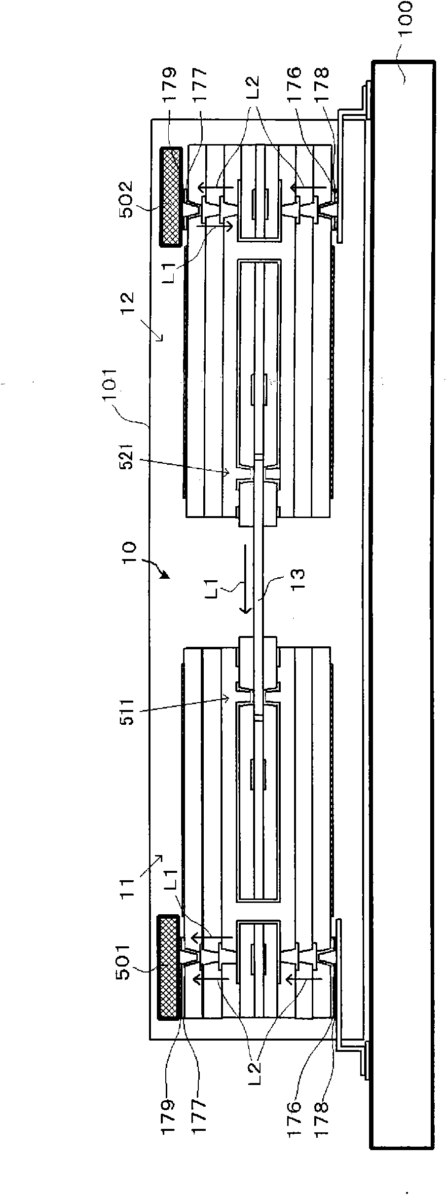
[0076] Such as figure 1 as well as figure 2 ( figure 1 As shown in the plan view structure and cross-sectional structure in A1-A1 cross-sectional view), the electronic device of this embodiment has a rigid-flex circuit board 10 and, for example, a rectangular package 101 . The flex-rigid circuit board 10 is surface-mounted, for example by soldering, on the surface of the rigid motherboard 100 and sealed into the package 101 . The motherboard 100 has a size capable of mounting a plurality of printed circuit boards. Here, as the motherboard 100 , a rigid printed circuit board having a larger wiring pitch (wider pitch width) than the rigid substrates 11 and 12 is used. In addition, the motherboard 100 is a printed circuit board on which connection terminals connectable to the printed circuit board are mounted. Also included in the mothe...


PUM


Abstract

A flex-rigid wiring board including a rigid printed wiring board having a rectangular shape and having a rigid base material and a conductor, and a flexible printed wiring board having a flexible base material and a conductor formed over the flexible base material. The conductor of the flexible printed wiring board is electrically connected to the conductor of the rigid printed wiring board. The flexible printed wiring board is connected to the rigid printed wiring board and extends from one or more sides of the rectangular shape of the rigid printed wiring board such that the flexible printed wiring board extends in a direction which makes an acute angle with respect to one or more sides of the rectangular shape of the rigid printed wiring board.

Description

technical field [0001] The present invention relates to a bendable rigid-flex circuit board partially composed of a flexible substrate and electronic equipment using the rigid-flex circuit board. Background technique [0002] It is known that in conventional electronic equipment, a rigid substrate on which electronic components are mounted is sealed in an arbitrary package (PKG), and mounted on a motherboard by, for example, pin connection or solder connection. For example, Patent Document 1 discloses a structure in which a plurality of rigid substrates mounted on a motherboard are electrically connected to each other. In detail, as Figure 40 As mentioned above, the connectors 1004 a and 1004 b are provided on the surfaces of the rigid substrates 1001 and 1002 mounted on the motherboard 1000 . Furthermore, the flexible substrate 1003 is connected by the connectors 1004a and 1004b. In this way, these rigid substrates 1001 , 1002 and electronic components 1005 a , 1005 b mo...

Claims


Application Information

Patent Timeline
Patent Type & Authority Patents(China)
IPC IPC(8): H05K3/46H05K1/14
CPCH05K2201/09245H05K3/3436H05K2201/09272H05K1/185H05K2203/049H05K2201/10265H05K2201/09236H05K2201/052H05K3/4602H05K1/16H05K3/325H05K2201/09254H05K2203/0455H05K2201/09109H05K3/4691H05K3/3421H05K1/141H05K2201/096H05K2201/09127
Inventor 匂坂克己
Owner IBIDEN CO LTD
Why Eureka
Try Eureka