Check patentability & draft patents in minutes with Patsnap Eureka AI!

Supercapacitor with movable separator and method of operating a supercapacitor

a supercapacitor and separator technology, applied in the field of supercapacitors, can solve the problems of micromachining process, inconvenient current filling of electrolyte chambers, and contamination of inner chambers by particles

Active Publication Date: 2017-05-04
STMICROELECTRONICS SRL
View PDF0 Cites 0 Cited by
  • Summary
  • Abstract
  • Description
  • Claims
  • Application Information

AI Technical Summary

Benefits of technology

The patent describes a way to cool down a supercapacitor by using an electrolytic solution that flows through the supercapacitor. This helps to maintain the temperature of the supercapacitor and improve its performance.

Problems solved by technology

Current techniques for filling the chamber with electrolyte are not optimal.
In particular, known techniques, which envisage opening of through holes for fluidic access to the chamber (used for introducing the electrolyte), and subsequent closing of said holes, are carried out according to known steps of micromachining of semiconductor materials (e.g., photolithography and etching), with the consequence that the inner chamber may be contaminated by particles deriving from the micromachining process.
Further, the step of closing of the holes for fluidic access to the chamber is, according to the known art, inconvenient.
Further, it may be noted that it is further inconvenient to dispense sealant material in the case where the holes for access to the inner chamber are made in the area of both of the electrodes (i.e., on both sides of the inner chamber).
This would require the use of systems specifically provided for the purpose, with a further economic burden.
Finally, there are evident the difficulties in handling the wafer in the step that follows introduction of the electrolyte into the inner chamber and that precedes closing of the holes in order to minimize undesirable leakage of electrolyte.

Method used


Image

  • Supercapacitor with movable separator and method of operating a supercapacitor
  • Supercapacitor with movable separator and method of operating a supercapacitor
  • Supercapacitor with movable separator and method of operating a supercapacitor

Examples


Embodiment Construction

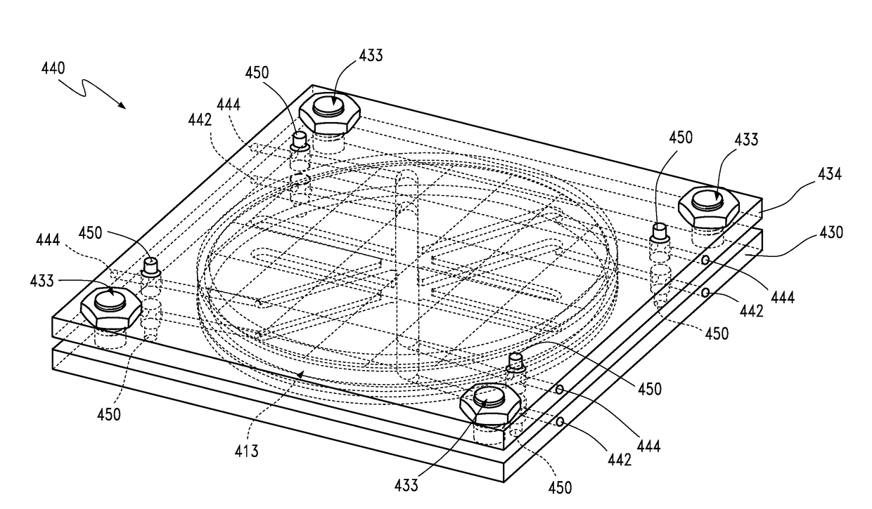
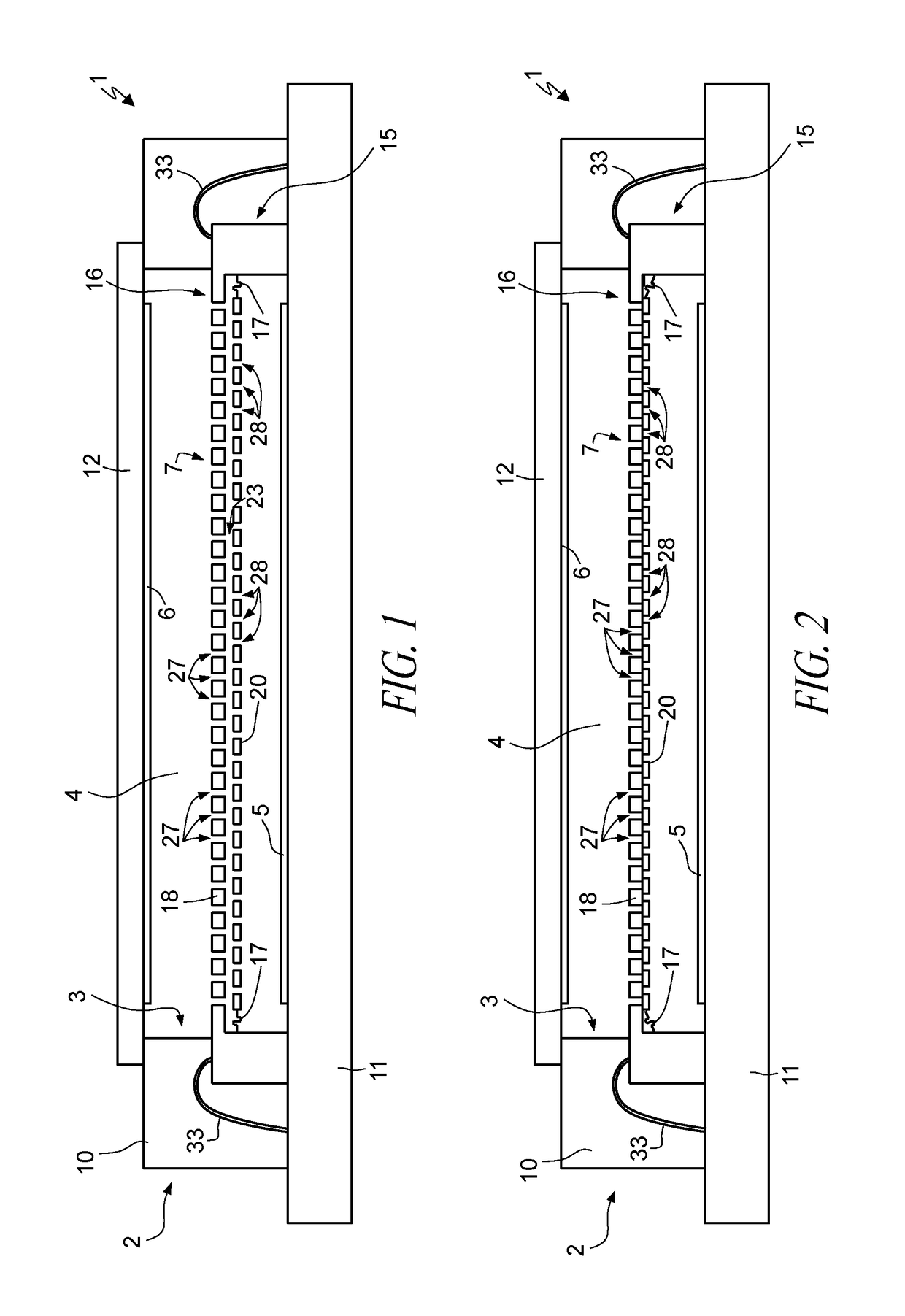
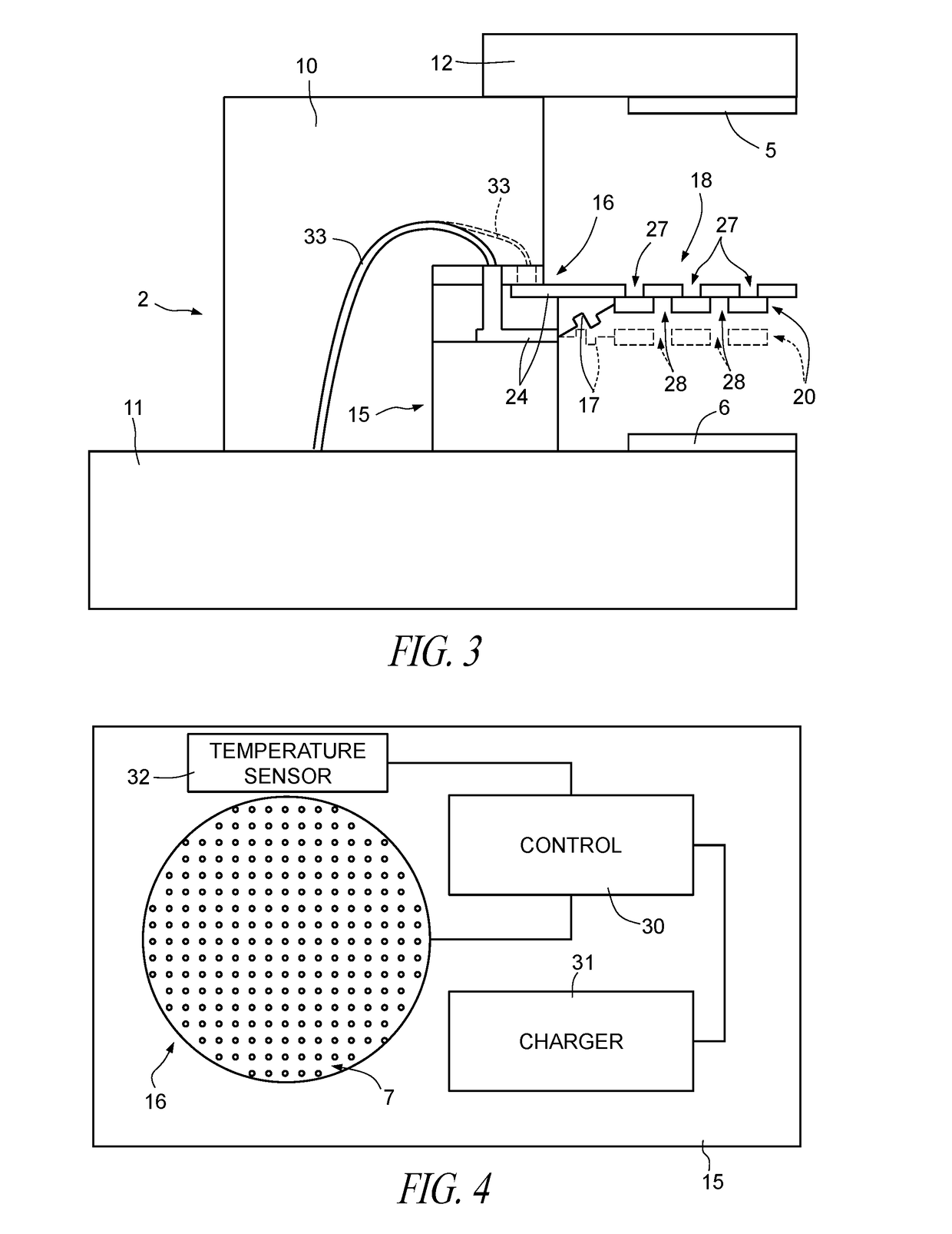
[0077]With reference to FIGS. 1-3, a supercapacitor according to one embodiment of the present disclosure is designated by the number 1 and comprises a shell 2, a chamber 3, which is defined in the shell 2 and contains an electrolyte 4, a first electrode 5, a second electrode 6 and a separator 7.

[0078]In one embodiment, the shell 2 comprises a frame structure 10, arranged on a base 11 and closed by a lid 12 on a side opposite to the base 11. The frame structure 10, the base 11 and the lid 12 define walls of the chamber 3.

[0079]The frame structure 10, made, for example, of polymeric material, has a through cavity and defines the chamber 3 laterally. In one embodiment, the frame structure and the base may be provided by a premolded package structure.

[0080]The chamber 3 is closed and sealed on opposite sides by the base 11 and by the lid 12 and is filled with the electrolyte 4. The first electrode 5 and the second electrode 6 are arranged on the base 11 and on the lid 12, respectively ...


PUM


Abstract

A supercapacitor including: a shell; a chamber in the shell; a first electrode and a second electrode on respective walls of the chamber; and a separator arranged between the first electrode and the second electrode through the chamber. The separator includes a first perforated membrane and a second perforated membrane, which is movable with respect to the first membrane between a first position, in which the first membrane and the second membrane are separate and a second position, in which the first membrane and the second membrane are in contact and coupled for rendering the separator impermeable.

Description

BACKGROUND[0001]Technical Field[0002]The present disclosure relates to a supercapacitor with movable separator and to a method of operating a supercapacitor. The present disclosure also relates to a method of manufacturing a package for a supercapacitor, and a supercapacitor thus obtained.[0003]Description of the Related Art[0004]As is known, supercapacitors are devices for energy storage and are encountering an ever-increasing use in different sectors on account of their peculiar features. Supercapacitors are distinguished, in fact, both from conventional capacitors, owing to the higher density of energy stored (J / kg) and from batteries, owing to the higher power density (W / kg). As compared to batteries, in other words, supercapacitors are able to store and supply the energy stored in times that are much shorter, even though the energy totally available is lower.[0005]The fields of use of supercapacitors are extremely varied, both for low-voltage applications and for power applicat...

Claims


Application Information

Patent Timeline
IPC IPC(8): H01G11/18H01G11/52H01G11/78H01G11/22
CPCH01G11/18H01G11/78H01G11/52H01G11/22Y02E60/13H01G11/08H01G11/14H01G11/82
Inventor SCURATI, MARIO GIOVANNIMORELLI, MARCOFONTANA, FULVIO VITTORIO
Owner STMICROELECTRONICS SRL
Features
  • R&D
  • Intellectual Property
  • Life Sciences
  • Materials
  • Tech Scout
  • Unparalleled Data Quality
  • Higher Quality Content
  • 60% Fewer Hallucinations
Learn More