Broadband multiple layer dielectric resonator antenna and method of making the same

Active Publication Date: 2017-05-04
ROGERS CORP
View PDF9 Cites 33 Cited by
  • Summary
  • Abstract
  • Description
  • Claims
  • Application Information

AI Technical Summary

Benefits of technology

[0005]An embodiment includes a dielectric resonator antenna (DRA) having: an electrically conductive ground structure; a plurality of volumes of dielectric materials disposed on the ground structure having N volumes, N being an integer equal to or greater than 3, disposed to form successive and sequential layered volumes V(i), i being an integer from 1 to N, wherein vo

Problems solved by technology

Existing resonators and arrays employ patch antennas, and while such antennas may be suitable for their intended purpose, they also have drawbacks, such as limited bandwidth, limited efficiency, and therefore limited gain.
Techniques that have been employed to improve the bandwidth have typically led to expensive and complicated multilayer and multi-patch designs, and it remains challenging to achieve bandwid

Method used


Image

  • Broadband multiple layer dielectric resonator antenna and method of making the same
  • Broadband multiple layer dielectric resonator antenna and method of making the same
  • Broadband multiple layer dielectric resonator antenna and method of making the same

Examples


embodiment-2

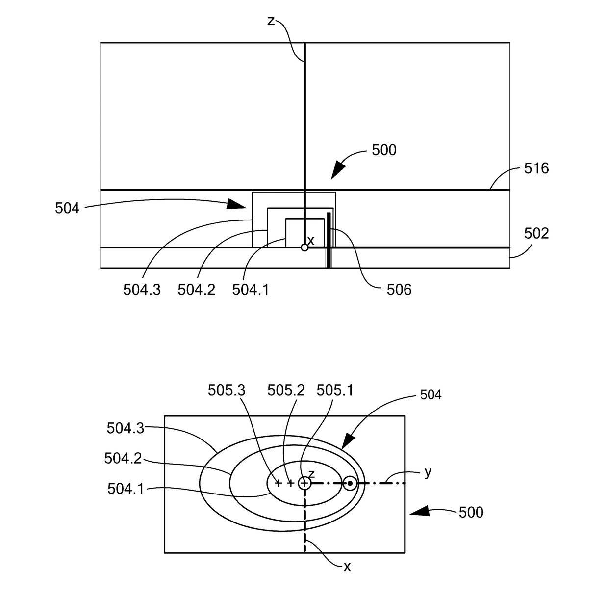
[0256] The DRA of Embodiment-1, wherein each successive volume V(i+1) forms a layered shell disposed over and completely 100% embedding volume V(i).

embodiment-3

[0257] The DRA according to any preceding Embodiment, wherein volume V(N) completely 100% embeds all volumes V(1) to V(N−1).

embodiment-4

[0258] The DRA according to any preceding Embodiment, wherein the signal feed is disposed within an opening of the ground structure in non-electrical contact with the ground structure, and is disposed within one of the plurality of volumes of dielectric materials.


PUM


Abstract

A method for the manufacture of a dielectric resonator antenna (DRA) or array of DRA's, the DRA having: an electrically conductive ground structure; a plurality of volumes of dielectric materials disposed on the ground structure having N volumes, N being an integer equal to or greater than 3, disposed to form successive and sequential layered volumes V(i), i being an integer from 1 to N, wherein volume V(1) forms an innermost volume, wherein a successive volume V(i+1) forms a layered shell disposed over and at least partially embedding volume V(i), wherein volume V(N) at least partially embeds all volumes V(1) to V(N−1); and, a signal feed disposed and structured to be electromagnetically coupled to one or more of the plurality of volumes of dielectric materials. The method including molding at least one of the plurality of volumes of the dielectric material, or all of the volumes of the dielectric material.

Description

CROSS REFERENCE TO RELATED APPLICATIONS[0001]This application claims the benefit of priority of: U.S. Provisional Application Ser. No. 62 / 247,459, filed Oct. 28, 2015; U.S. Provisional Application Ser. No. 62 / 258,029, filed Nov. 20, 2015; and, U.S. Provisional Application Ser. No. 62 / 362,210, filed Jul. 14, 2016, all of which are incorporated herein by reference in their entireties.BACKGROUND OF THE INVENTION[0002]The present disclosure relates generally to a dielectric resonator antenna (DRA), particularly to a multiple layer DRA, and more particularly to a broadband multiple layer DRA for microwave and millimeter wave applications.[0003]Existing resonators and arrays employ patch antennas, and while such antennas may be suitable for their intended purpose, they also have drawbacks, such as limited bandwidth, limited efficiency, and therefore limited gain. Techniques that have been employed to improve the bandwidth have typically led to expensive and complicated multilayer and mult...

Claims


Application Information

Patent Timeline
IPC IPC(8): H01Q9/04H01Q1/42H01Q1/48H01Q5/50
CPCH01Q9/0485H01Q1/48H01Q1/422H01Q5/50H01Q21/30H01Q9/0492
Inventor PANCE, KRISTISPRENTALL, KARLWILLIAMS, SHAWN P.DAIGLE, ROBERT C.
Owner ROGERS CORP
Why Eureka
Try Eureka