Dielectric resonator and dielectric filter

a dielectric filter and dielectric resonator technology, applied in the direction of waveguide devices, resonators, basic electric elements, etc., can solve the problems of filter price increase, filter size reduction, and filter loss, and achieve the effect of reducing filter size, reducing filter cost, and reducing filter cos

Inactive Publication Date: 2004-07-13
NEC CORP +1
View PDF17 Cites 29 Cited by
  • Summary
  • Abstract
  • Description
  • Claims
  • Application Information

AI Technical Summary

Problems solved by technology

However, as dielectrics with low dielectric loss used in microwave region generally has a characteristic that dielectric loss thereof increases as dielectric constant becomes higher, size reduction of the filter maintaining insertion loss low has a certain limitation.
Further, as dielectrics with low loss as mentioned above is expensive, accordingly the filter becomes expensive when the filter provides more stages, that is, provides more dielectrics used therein.
And a filter relative to a second conventional example utilizing HE11 .delta. dual mode dielectric resonator for size reduction has a problem that lots of undesired modes excited in the vicinity of pass band result in spurious characteristic deteriorated easily, because HE11 .delta. is not the dominant mode.
On the other hand, for example, in the event that a dielectric filter used in microwave communications, and the like is composed, it is conventionally hard to reduce size and weight of a dielectric filter, because many resonators

Method used


Image

  • Dielectric resonator and dielectric filter
  • Dielectric resonator and dielectric filter
  • Dielectric resonator and dielectric filter

Examples


example 2

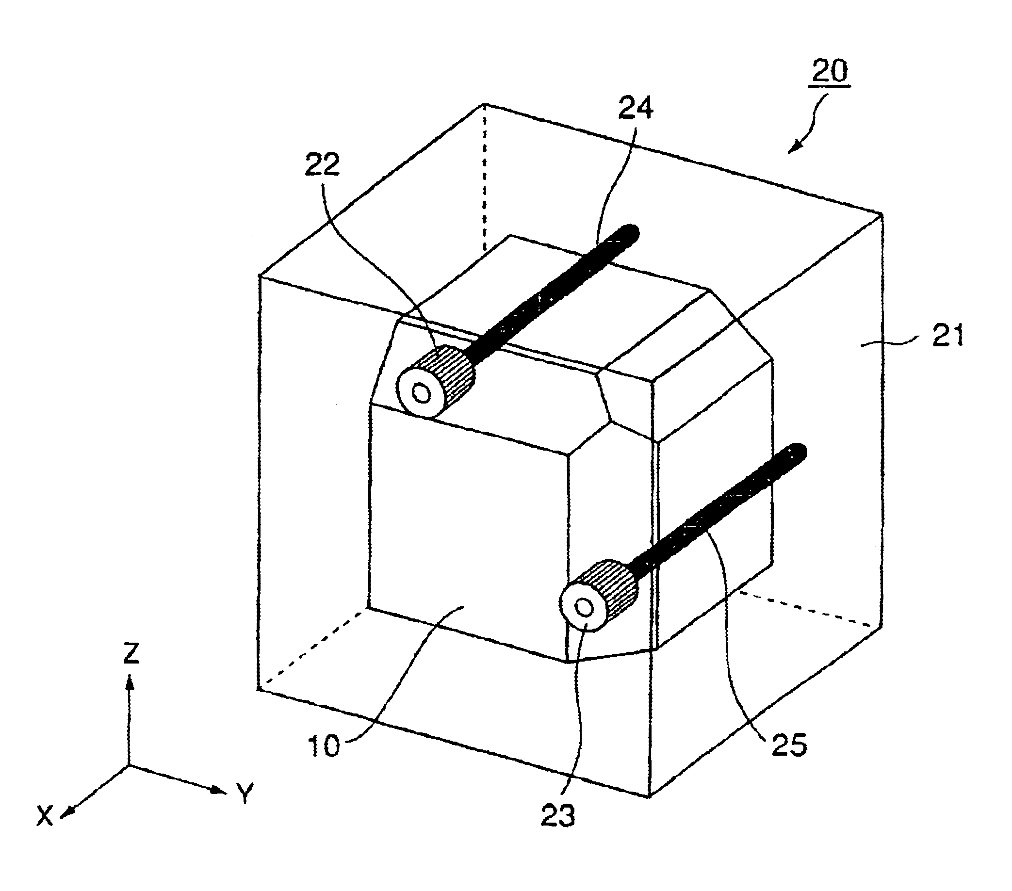
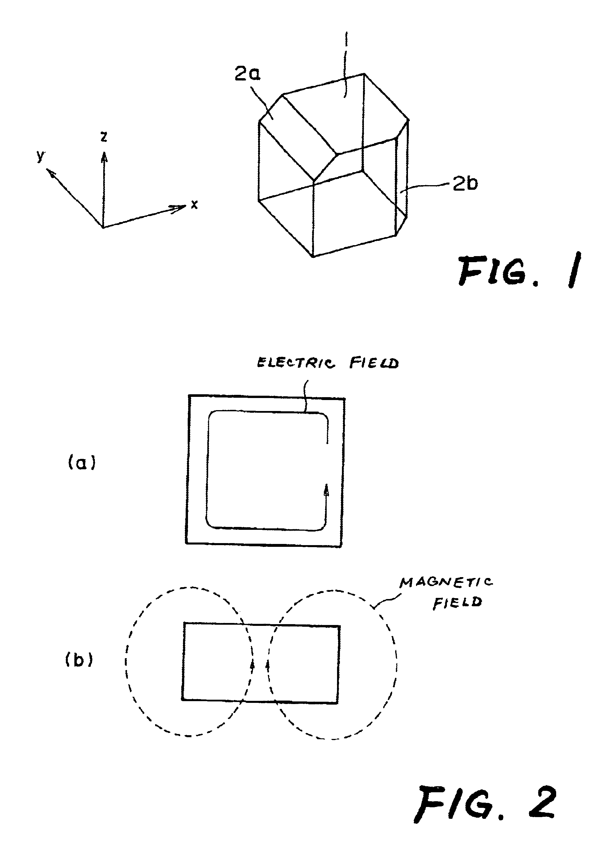
FIG. 10 is a perspective diagram of a dielectric filter of an example 2 utilizing two of the above-mentioned triple mode dielectric resonators therein. That is, the dielectric filter of the example 2 is composed of two of the triple mode dielectric resonators shown in FIG. 1 putting a predetermined distance to each other disposed in a longitudinal cut-off waveguide 3 and rod-type antennas 8, antennas 8 having both end surfaces opened by input-output terminals 9, terminals 9 provided in a direction of axis x from the above-mentioned both end surfaces in longitudinal direction of the cut-off waveguide 3 respectively. A screw 4 contacting with upper surface of the cut-off waveguide 3 by one end is disposed between the two triple mode dielectric resonators in order to adjust the coupling between the dielectrics. Exemplary mounts 3a for supporting each resonator (dielectric block 1) are shown.

In the dielectric filter of the example 2, two of the triple mode dielectric resonators are prov...

example 3

FIG. 11 is a perspective diagram of a dielectric filter of an example 3 which is a dielectric filter utilizing the above-mentioned triple mode dielectric resonators providing a metallic partition 5 between two dielectric blocks 1 therein. That is, in the same manner as the above-mentioned example 2, the dielectric filter of the example 3 is composed of two of the triple mode dielectric resonators shown in FIG. 1 disposed in a longitudinal cut-off waveguide 3 and rod-type antennas 8, 8 having both end surfaces opened by input-output terminals 9, 9 provided in a direction of axis x from the above-mentioned both end surfaces in longitudinal direction of the cut-off waveguide respectively. In the present example, a metallic partition 5 is provided instead of a screw 4 of the example 2 between the two dielectric resonators. And as shown in FIG. 11, a surface 2b having the above-mentioned another ridge portion chamfered on one side of the dielectric block 1 is formed in a different positi...

example 4

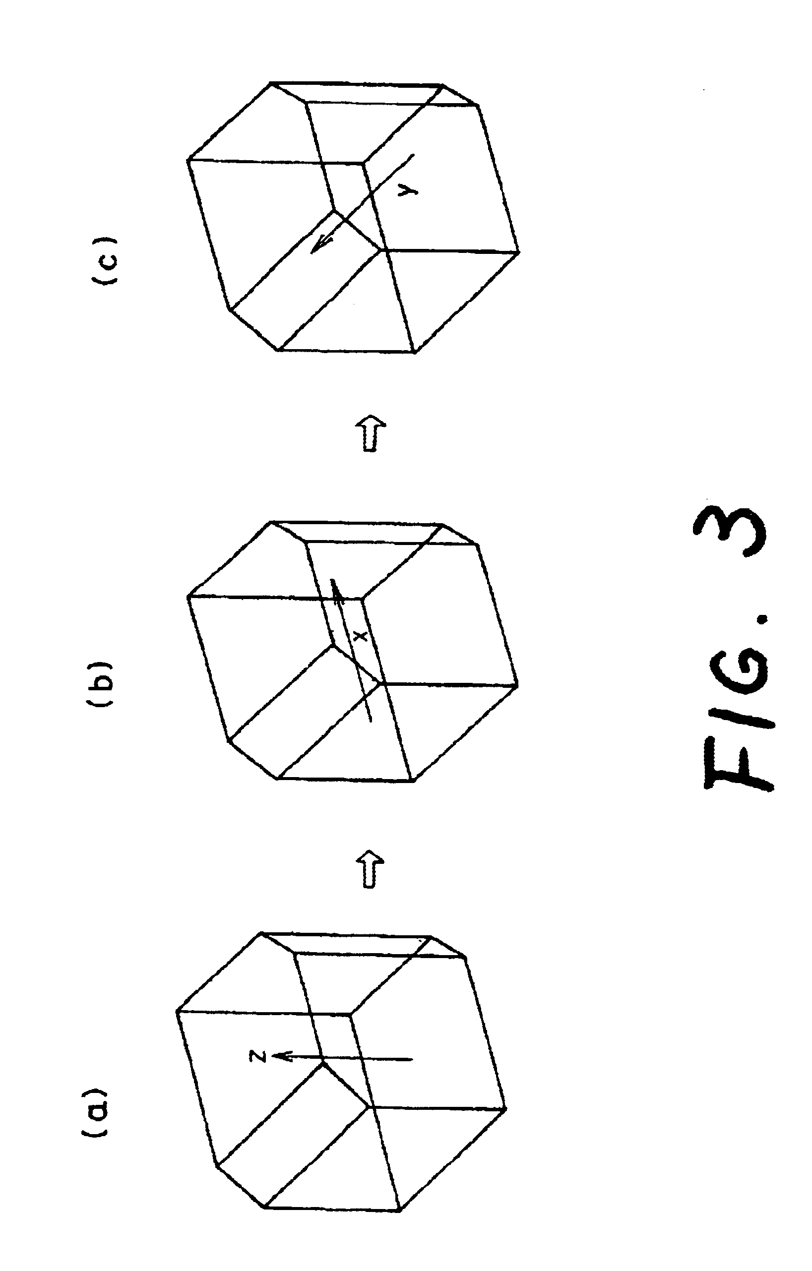
FIG. 13 is a diagram for showing a method of adjusting the above-mentioned dielectric filter by a metal rod. Actually, a screw is used as a metal rod and the adjustment is conducted by putting in and out of the screw. The metal rod acts on a magnetic field leaking from dielectrics. As the metal rod in the position of 6a in FIG. 13 has interlinkage with magnetic flux of the resonance in the event of resonance in direction x, the magnetic field is intensified and resonant frequency becomes lower. The phenomenon is equal to a growth of equivalent inductance in a parallel resonant circuit. In the same manner, 6b lowers the resonant frequency of y direction. Conventionally, as a metal rod in a position of 6c raises the resonant frequency, frequency can be adjusted in wide range by combination of the adjustment in the three directions x, y, z. With regard to the coupling, as 7a weaken the coupling of resonance in direction x and in direction y while 7b works for intensifying the coupling,...


PUM


Abstract

A dielectric resonator (10) having three surfaces formed by chamfering three ridged portions sharing an apex of a dielectric block and another three surfaces adjacent respectively thereto, in which each of the chamfered surfaces and the adjacent surfaces thereto offers an angle of 45 degrees and an area ratio of the chamfered surfaces with respect to the adjacent surfaces is 45% is mounted in a cut-off waveguide of a generally rectangular parallelopiped (21) and feeding probe (24) and (25) are provided for composing a dielectric filter.

Description

The present invention relates to a dielectric filter used in radio communications, and the like at high frequency band as microwave band; quasi-microwave band, and the like and a dielectric resonator used in the dielectric filter, and more particularly to a triple mode dielectric resonator in which three resonant modes are available in one dielectric block and a dielectric filter using the dielectric resonator therein.TECHNICAL BACKGROUNDConventionally, a dielectric filter which providing a cut-off waveguide with cylindrical or rectangular parallelopiped dielectrics disposing successively therein and utilizing resonance of a cylindrical TE01 .delta. mode or a rectangular TE11 .delta. mode of dielectrics is utilized widely in filters requiring low loss and size reduction, because the dielectric filter has high unloaded Q and can be reduced in size easier than waveguide type filter (a first conventional example). A resonance of the mode is generated by an electric field repeating refl...

Claims


Application Information

Patent Timeline
IPC IPC(8): H01P1/208H01P7/10H01P1/20
CPCH01P1/2084H01P1/2086H01P7/105H01P1/20
Inventor ISOMURA, AKIHIROFURUTA, ATSUSHIHWANG, JAE-HO
Owner NEC CORP
Why Eureka
Try Eureka