Gear system for electric vehicle

a technology for electric vehicles and gear systems, applied in the field of gear systems, can solve problems such as negative radio reception effects, and achieve the effect of suppressing noise propagation and reducing noise radiation to the exterior

Active Publication Date: 2017-05-04
NISSAN MOTOR CO LTD
View PDF7 Cites 5 Cited by
  • Summary
  • Abstract
  • Description
  • Claims
  • Application Information

AI Technical Summary

Benefits of technology

[0009]The present invention has been achieved in view of the aforementioned problem. An object of the present invention is to provide a power transmission device applicable to electric vehicles, which suppresses noise propagation from an inverter through a power transmission to drive shafts and suspensions, thereby reducing noise radiation to the exterior.Technical Solution

Problems solved by technology

It is known that, in an electric vehicle equipped with a motor as a driving power source, an inverter for controlling the motor generates high-frequency noise (or referred to as “radio noise”) and a motor drive system including a power transmissions, suspensions and such can be antennas to radiate the high-frequency noise, which cause negative effect on radio reception.

Method used


Image

  • Gear system for electric vehicle
  • Gear system for electric vehicle
  • Gear system for electric vehicle

Examples


first embodiment

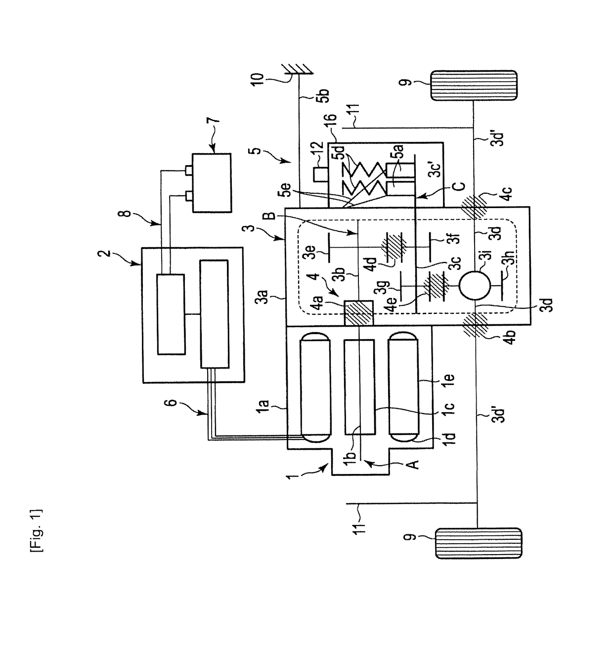
[0023]Referring to FIG. 1, a power transmission device for an electric vehicle according to the present invention will be described.

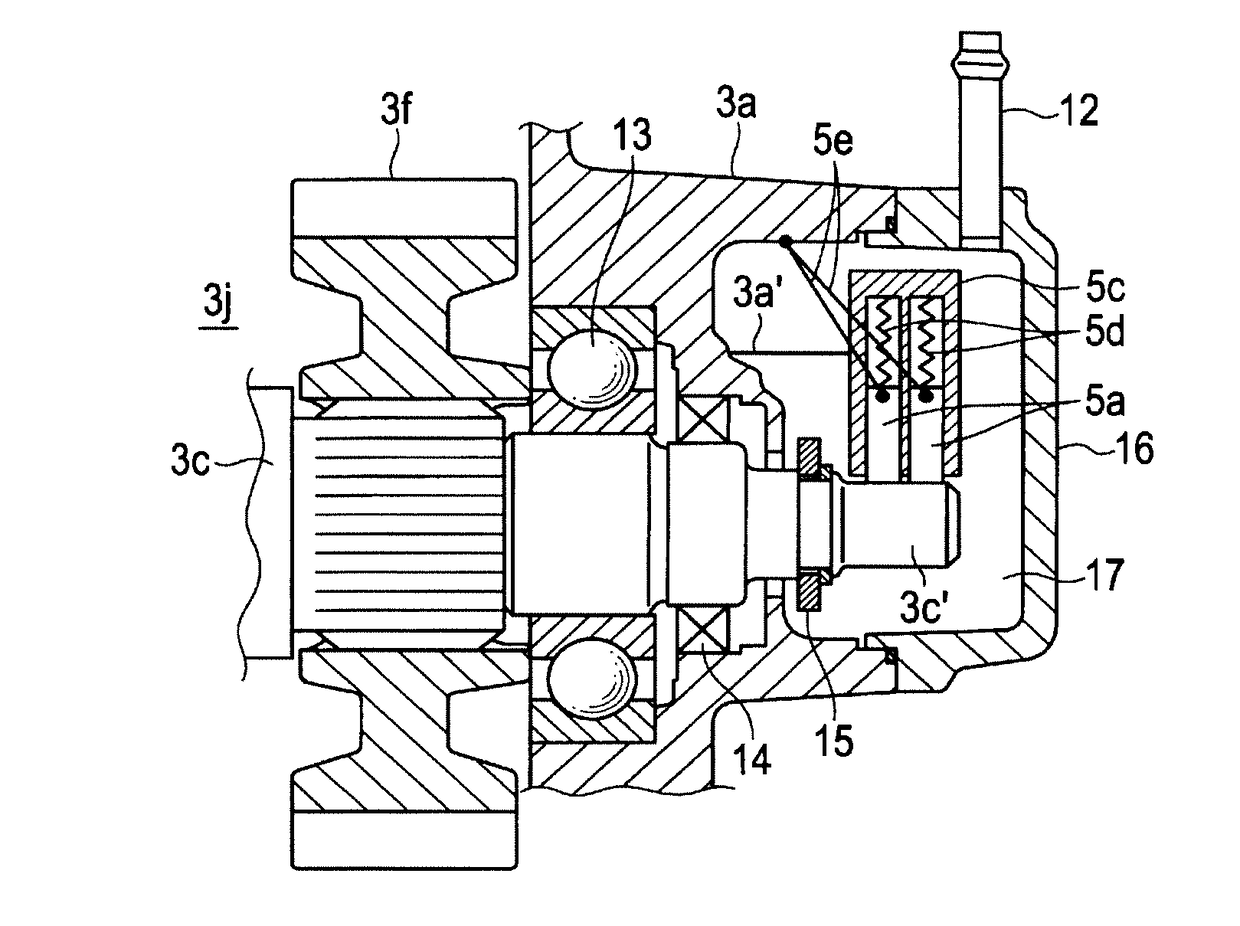
[0024]The power transmission device of the first embodiment is comprised of a motor 1, an inverter 2, a first gear set 3 including a plurality of couplings and meshing parts 4 functioning as resistors, and a grounding path 5.

[0025]The motor 1 is comprised of a motor housing 1a, a rotor shaft 1b rotatably supported by the motor housing 1a, a rotor 1c drivingly coupled with the rotor shaft 1b, and stators 1e fixed to the motor housing 1a. Each stator 1e has an electric coil 1d coiled therearound. The rotor 1c is accordingly comprised of a plurality of permanent magnets, thereby being rotated by a magnetic field generated by the coils 1d. Specifically, any permanent magnet synchronous motor may be applied to the motor 1.

[0026]The inverter 2 is connected with the motor coils 1d of the motor 1 via a three-phase power cable 6, and is in turn connected with a ...

third embodiment

[0055]Alternatively, epicyclic gearing or planetary gearing may be used instead of the aforementioned reduction gears of a parallel shaft system. FIG. 7 illustrates a third embodiment in which a gear set 33 with planetary gearing is used.

[0056]The power transmission device of the third embodiment is comprised of a motor 1, an inverter 2, the gear set 33 including electrically resistive elements 4, and a grounding path 5. Aside from the gear set 33, those as described earlier can be applied to these components 1, 2 and 5 and therefore detailed descriptions thereof will be omitted.

[0057]The gear set 33 intervenes between a rotor shaft 1b of the motor 1 and output shafts 33d, thereby transmitting torque from the rotor shaft 1b to the output shafts 33d.

[0058]The gear set 33 includes a combination of shafts and meshing gears, all of which are in general carried by a gear casing 33a. The shafts include an input shaft 33b, a cylindrical shaft 33c coaxial with the input shaft 33b and an ou...


PUM


Abstract

A power transmission device for a vehicle is comprised of a motor including a rotor shaft and a stator having an electromagnetic coil; an inverter configured to generate an alternating current, the inverter being connected with the coil to controllably rotate the rotor shaft relative to the stator; a gear set including an input shaft coupled with and rotated by the rotor shaft, an output shaft and gears so meshed as to transmit torque of the input shaft to the output shaft; and a grounding path electrically connecting a part of the gear set with a body of the vehicle, the part being so disposed as to have the input shaft electrically interposed between the part and the rotor shaft.

Description

[0001]This application is a continuation of U.S. application Ser. No. 13 / 697,663, filed Nov. 13, 2012, which claims benefit of priority from the prior Japanese Application No. 2010-121145, filed on May 27, 2010; the entire contents of all of which are incorporated herein by reference.TECHNICAL FIELD[0002]The present invention relates to a gear system applicable to electric vehicles with measures for preventing radiation of high-frequency noise.BACKGROUND ART[0003]It is known that, in an electric vehicle equipped with a motor as a driving power source, an inverter for controlling the motor generates high-frequency noise (or referred to as “radio noise”) and a motor drive system including a power transmissions, suspensions and such can be antennas to radiate the high-frequency noise, which cause negative effect on radio reception.[0004]The following document discloses a related art, which proposes having a brush in electrical contact with an output shaft of a motor and grounding the b...

Claims


Application Information

Patent Timeline
Patent Type & Authority Applications(United States)
IPC IPC(8): H02K11/40F16H3/091B60L11/18H02K7/116H02K11/33F16H57/02B60L15/20B60L50/16
CPCH02K11/40F16H57/02F16H3/091B60L15/2054F16H2057/02043H02K11/33B60L11/18F16H2057/02034H02K7/116H02K21/14B60L2270/147B60L50/60Y02T10/64Y02T10/72Y02T10/70B60L15/00F16H1/04B60Y2200/91
Inventor OKADA, TOMOHIROOIKAWA, NAOAKISARUWATARI, TAKAHIROIKEDA, TATSUHIKONAKAYAMA, KENSOEDA, KAZUHIKOINADA, AKINORI
Owner NISSAN MOTOR CO LTD
Why Eureka
Try Eureka