Liquid sample collection device

a collection device and liquid sample technology, applied in medical science, surgery, vaccination/ovulation diagnostics, etc., to achieve the effect of reducing the complexity, reducing the failure rate of the device, and becoming resistant to shaking and overturning

Inactive Publication Date: 2017-05-11
NORTHERN BANK LTD
View PDF26 Cites 0 Cited by
  • Summary
  • Abstract
  • Description
  • Claims
  • Application Information

AI Technical Summary

Benefits of technology

[0013]This invention provides a liquid sample collection device with no moving parts that contact the sample, capable of targeting and isolating a first portion of a liquid stream. The device comprises a meandering channel, which forms part of a liquid supply conduit supplying a liquid to be collected from an inlet port generally downwardly into a collection chamber. The collection chamber features an air vent port that connects the collection chamber to the atmosphere and acts as a pressure relief channel. As a liquid sample to be collected flows from the inlet port, through the meandering channel, and into the collection chamber, the air displaced escapes to the atmosphere via the vent port. However, once the vent port is obstructed, any additional liquid entering the collection chamber displaces air back up the meandering channel, where it becomes trapped in a local high point in the channel, thereby forming an air lock. The air lock prevents further liquid entering the collection chamber, and any additional liquid overflows the inlet port and is directed to waste.
[0014]In a particularly preferable embodiment, the air vent port is adapted to be closed, in use, by liquid collected in the collection chamber. In these embodiments, the air vent port may be positioned such that, as liquid collects within the collection chamber, the rising liquid level eventually obstructs the air vent port and engages the air lock. This embodiment is particularly preferable as it results in a device which can target and isolate a first portion of a liquid stream with no moving parts at all, reducing the complexity, manufacture cost and failure rate of the device. While this is prefe

Problems solved by technology

However, once the vent port is obstructed, any additional liquid entering the collection chamber displaces air back u

Method used


Image

  • Liquid sample collection device
  • Liquid sample collection device
  • Liquid sample collection device

Examples


Embodiment Construction

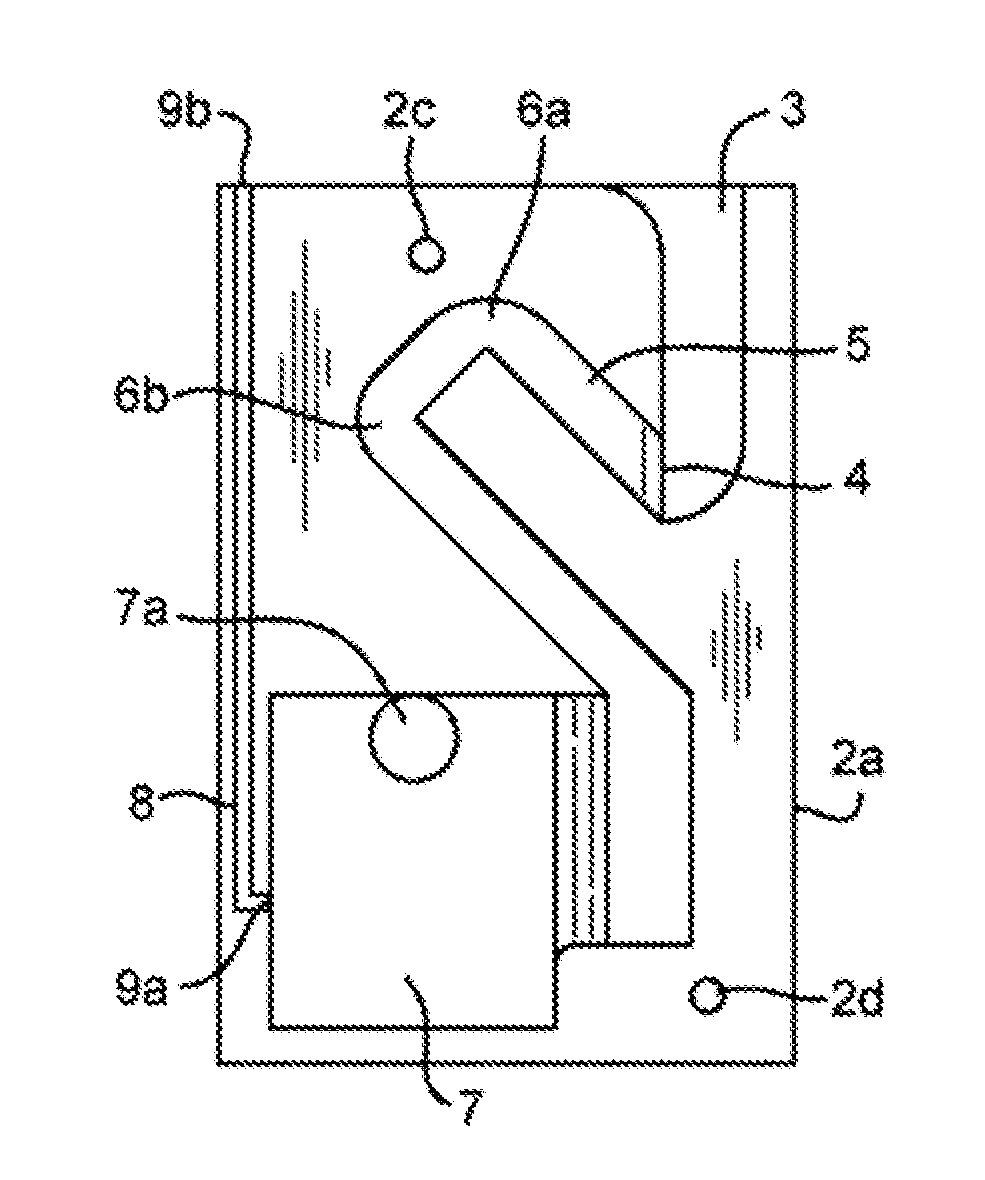
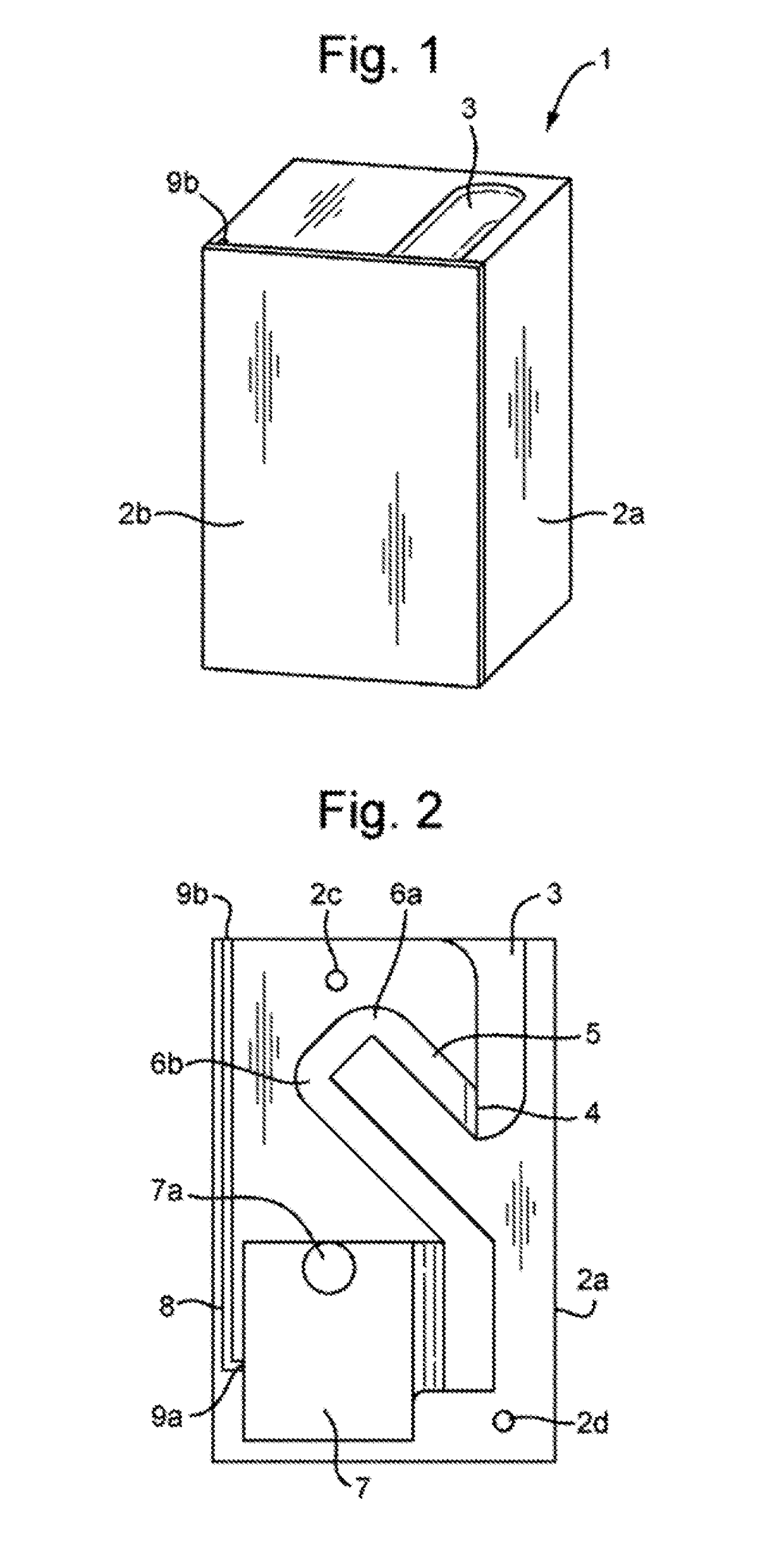
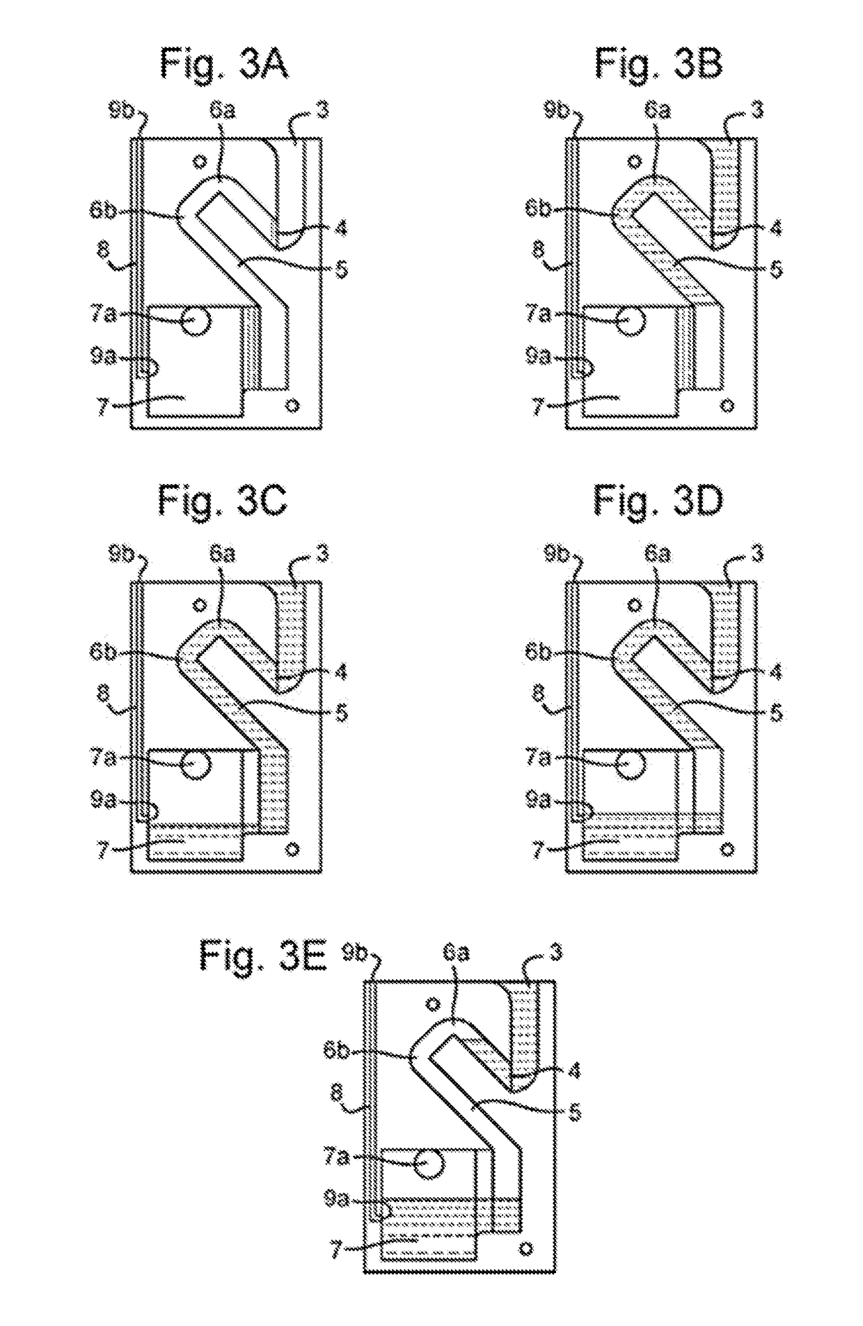
[0032]A liquid sample collection device 1 comprising a single meander is shown in FIGS. 1, and 2. The liquid sample collection device 1 comprises a solid cuboidal body 2a with dimensions of approximately 3 cm wide, 5 cm high and 4 cm deep. The device 1 also comprises a cover 2b which covers a front face of the body of the device 2a. The front face of the body of the device 2a has a series of recesses which partially define a number of features in its surface. These features include an inlet slot 3, a channel 5, a collection chamber 7, and pressure relief channel 8. The features partially defined by these recesses are completed and made internal to the device when the cover 2b is attached to the front of the body of the device 2a. The body of the device 2a also includes two location features 2c, 2d for aligning and attaching the cover 2b using corresponding location features (not shown) on the cover.

[0033]The body of the device 2a is a single piece of material, preferably formed into...


PUM


Abstract

A liquid sample collection device is provided. The liquid sample collection device comprises a housing including a liquid collection chamber, and a liquid supply conduit extending from an inlet port and in use generally downwardly to the collection chamber, wherein the collection chamber includes an air vent port located such that in use liquid supplied to the collection chamber through the liquid supply conduit displaces air through the air vent port, and wherein the liquid supply conduit follows a meandering path including at least one air trap section defined at the junction between portions of the conduit extending with upward and downward components respectively, whereby in use once the air vent port is closed, air is displaced along the liquid supply conduit until it is trapped by the air trap section thereby preventing further liquid flow through the conduit.

Description

FIELD OF THE INVENTION[0001]The invention relates to a liquid sample collection device for targeting, separating and isolating a specific portion of a continuous stream of liquid to be collected.DESCRIPTION OF BACKGROUND ART[0002]Biomarkers, micro-organisms, proteins, DNA and chemicals are often suspended in a liquid or transported by a liquid flow. It is often desirable to collect such liquids for storage, processing or to detect the presence, concentration, state, or other property of the suspended matter. Collecting such a liquid often requires instigating a flow or stream of the liquid from its reservoir to a collection receptacle. An example of a liquid containing suspended matter which is collected from a liquid stream is urine.[0003]Traditionally urine is collected by asking the patient to fill a cup to a level marked on the side. This is often imprecise, and it is common for patients to overfill or underfill the cup. Furthermore, in urine collection for STI (sexually transmi...

Claims


Application Information

Patent Timeline
IPC IPC(8): A61B10/00A61F5/441
CPCA61F5/441A61B10/007
Inventor JACKSON, STUARTMCCONNELL, IVANLAMONT, JOHNFITZGERALD, STEPHEN PETER
Owner NORTHERN BANK LTD
Why Eureka
Try Eureka