
Cork Extractor

Active Publication Date: 2017-05-11
TRUE FABTIONS
View PDF6 Cites 4 Cited by
  • Summary
  • Abstract
  • Description
  • Claims
  • Application Information

AI Technical Summary

Benefits of technology

The invention provides a mechanism for positioning the needle centrally through the cork for optimal removal and stabilizing the bottle to facilitate single-handed use of the extraction device. This is achieved through a positioning section at the terminal end of the extraction device that extends beyond the tip of the needle and a resistance means that maintains the extraction device in a decompressed state. The resistance means introduces a safety feature and ensures the device is stable without requiring the user's other hand. The invention also provides a method for facilitating removal of an extracted cork from the needle, as well as enhanced safety when the device is not in use. The containing section slidably engages with the sliding section to allow axial penetration of the needle through the cork and prevent rotation of the needle through the cork.

Problems solved by technology

Additionally, the use of a worm compromises the integrity of the cork.
A cork could fragment during the extraction process if the worm is not properly placed in the center of the cork or if improperly driven through the cork in an angled manner.
This could require multiple attempts to extract the cork and potentially an altogether failed extraction.
Even with proper use, the worm displaces a distinct portion of the cork creating the potential for particles of cork to fall into the wine contained therein creating impurities.
Recently electric openers eliminate the leverage function, however these extractors still use a worm to penetrate the cork and the use of a worm inherently requires the bottle opener to be rotationally driven through the cork, thereby requiring a second hand to stabilize the bottle.
Therefore, these methods only eliminate part of the problems inherent in the traditional corkscrew.
However, extractors incorporating injected compressed fluid leave significant room for improvement.
For example, other extractors provide minimal guidance for centering the needle through the surface area of the cork, such that cork removal maybe be hindered and preservation of the cork maybe comprised by not maintaining a linear or central path through the cork.
An additional problem is that due to the length of needle required to penetrate through the length of the cork, the needle often remains exposed posing a safety hazard to users while the extractor is not engaged with the bottle.
A few inadequate designs offer to address this issue by extending a component of the device to extend the length of the needle, however, in these embodiments the needle is not guarded from all directions and still remains fully exposed on more than one side while the extractor is in a resting positioning.
Furthermore, any shield extending around the needle is limited by the height of the bottleneck.
Since the needle must inherently be of a length that extends at least partially beyond the length of the cork to inject fluid into the bottle, this would result in a portion of the sharp end of the needle remaining exposed.
One inadequate design introduces a shield that slides down to cover the needle.
Therefore, when the extractor is inverted, the jacket will slide toward the top of the device exposing the needle while the device is in a resting state impeding the efficacy of the safety mechanism.
Further, previous extractors typically rely on the user to forcibly pull an extracted cork from the needle.
This results in physical exertion and creates a potentially dangerous scenario due to the exposed needle.

Method used


Image

  • Cork Extractor
  • Cork Extractor
  • Cork Extractor

Examples


first embodiment

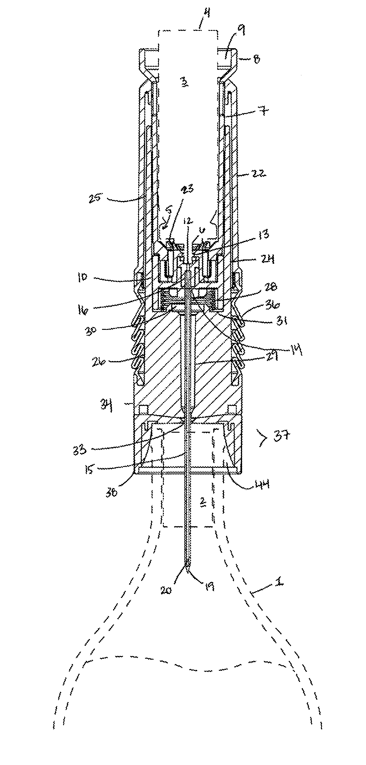
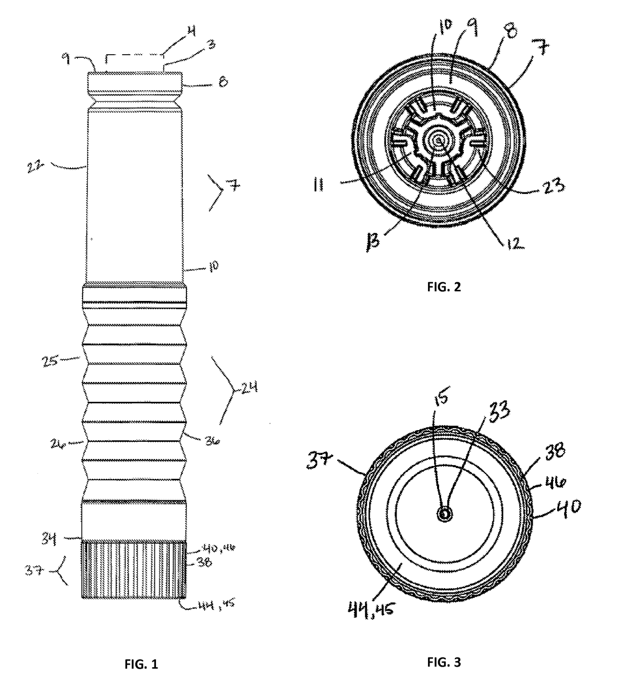
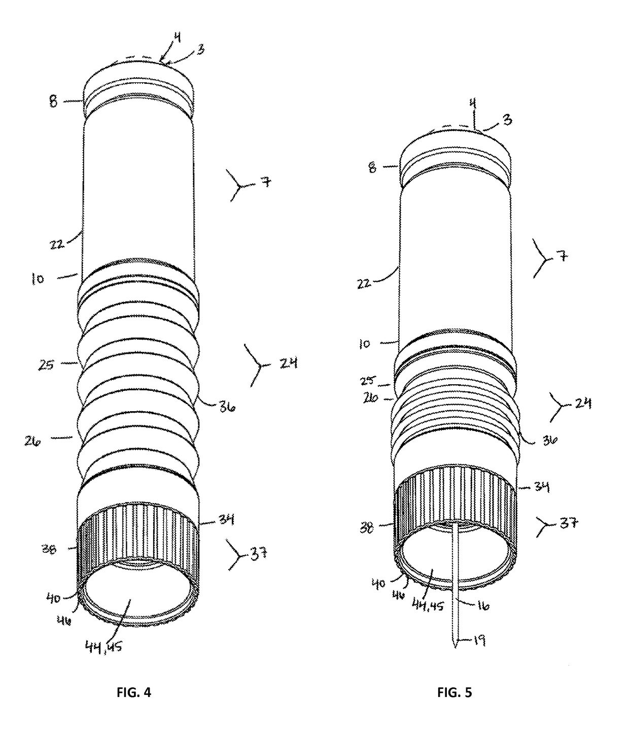
[0053]FIGS. 1-8 depict the extractor device wherein the primary function is extraction of the cork 2 based upon an improved structure. The extractor device includes a containing section 7 housing a compressed fluid container 3, a long hollow needle 15 affixed to the containing section 7 and extending longitudinally through a sliding section 24, a resistance means 28 housed in a sliding section 24 that is adapted to slidably engage with the containing section 7, and a positioning section 37 to engage with the bottle 1.

[0054]The general operation behind an extractor of this type is that a user grips the extractor device in a decompressed state with one hand, places the extractor device over the bottleneck 1 of a corked bottle 1, and applies a downward force against the resistance means 28 to penetrate the needle 15 through the cork 2. Once the extractor device is in this compressed state and the needle outlet 33 is exposed in the open section of the bottle 1. The user, then uses the t...

second embodiment

[0069]FIGS. 9-13 depict the extractor device, wherein the primary function is to remove the extracted cork 2 from the needle 15 whereupon it has been displaced during the extraction. All reference numbers are each selected to denote the same function as in the prior embodiments and are incorporated by reference herein. In this embodiment of the invention, the positioning section 37 has an interior section 39, an exterior section 40, and a tubular sleeve 41. In the preferred embodiment, the positioning section 37 has a substantially circular cross-section. The interior section 39 is defined as a portion of the positioning section 37 that fits within the second portion 26 of the sliding section 24 from the lower end 10 of the sliding section 24 up towards the needle inlet support 31. The interior section 39 has a rotational connection to the sliding section 24.

[0070]In an exemplary embodiment, the rotational connection is achieved between the interior section 39 and the second portion...


PUM


Abstract

An extractor device for use with a removable compressed fluid container having a containing section, sliding section, positioning section, and a hollow needle. A method of extracting a cork from a bottleneck utilizing a compressed fluid injected from a removable container, housed within a containing section of the device, to the bottle through a hollow needle affixed to the containing section of the device. The cork extractor device can include a rotationally projected component to forcibly displace a removed cork from the needle.

Description

FIELD OF THE INVENTION[0001]The present invention generally relates to an improvement of a cork extractor for wine bottles and the like, and more particularly, an improvement of cork extractors of the type that extract the cork by injecting pressurized fluid into a bottle or the like.BACKGROUND[0002]Additionally, the use of a worm compromises the integrity of the cork. A cork could fragment during the extraction process if the worm is not properly placed in the center of the cork or if improperly driven through the cork in an angled manner. This could require multiple attempts to extract the cork and potentially an altogether failed extraction. Even with proper use, the worm displaces a distinct portion of the cork creating the potential for particles of cork to fall into the wine contained therein creating impurities. Furthermore cork preservation is a benefit that also serves wine consumers who use the original cork to recork or “stop” the bottle and those who keep corks for displ...

Claims


Application Information

Patent Timeline
IPC IPC(8): B67B7/08
CPCB67B7/08
Inventor HUME, RYAN WILLIAM
Owner TRUE FABTIONS
Learn More