Information processing device and error detection method

Active Publication Date: 2017-05-11
NEC CORP
View PDF6 Cites 6 Cited by
  • Summary
  • Abstract
  • Description
  • Claims
  • Application Information

AI Technical Summary

Benefits of technology

[0020]The present invention may impro

Problems solved by technology

Second, the process monitoring device issues an alarm for the

Method used


Image

  • Information processing device and error detection method
  • Information processing device and error detection method
  • Information processing device and error detection method

Examples


first exemplary embodiment

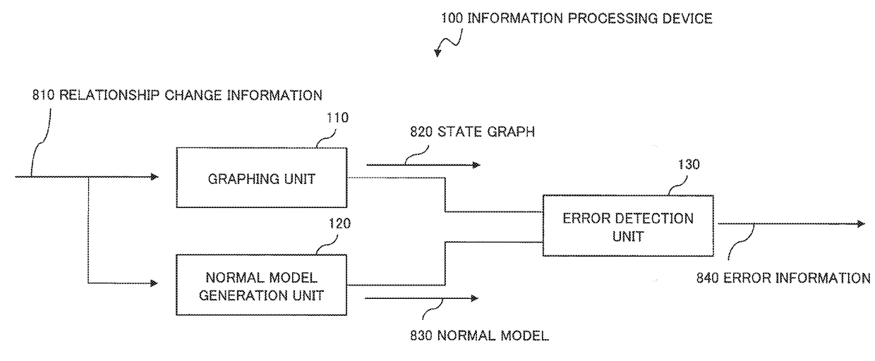
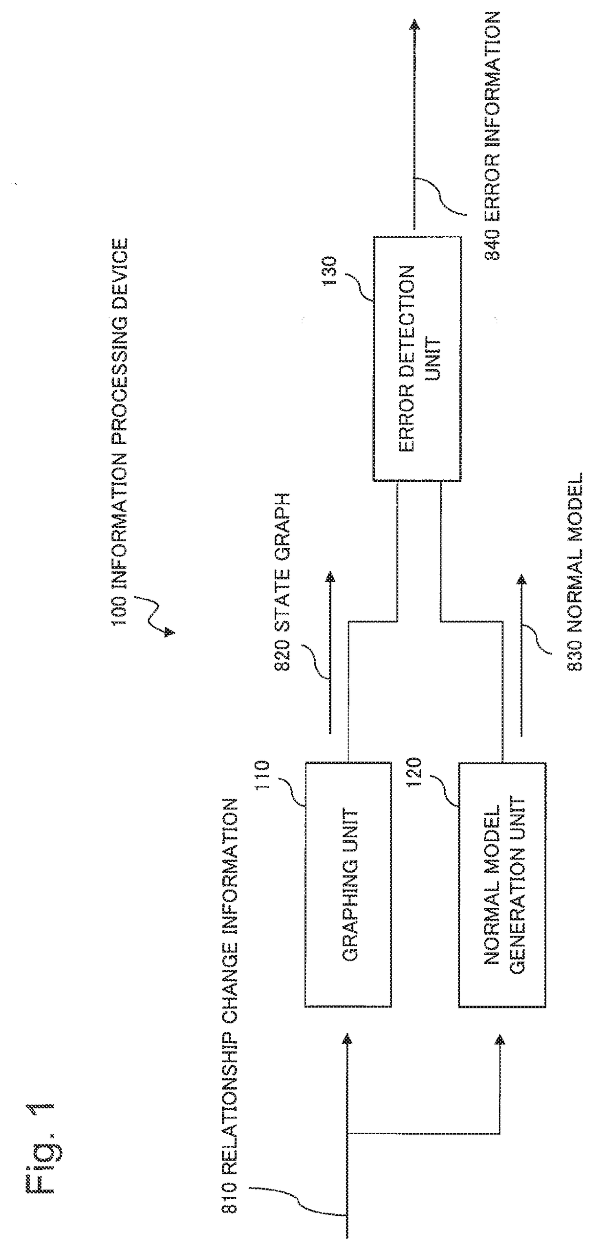
[0042]FIG. 1 is a block diagram illustrating the configuration of an information processing device 100 according to a first exemplary embodiment of the present invention.

[0043]The information processing device 100 according to the present exemplary embodiment includes a graphing unit 110, a normal model generation unit 120, and an error detection unit 130, as illustrated in FIG. 1. Components illustrated in FIG. 1 may be divided for each hardware-specific circuit or each function of a computer device. Components illustrated in FIG. 1 are assumed herein to be divided for each function of a computer device.

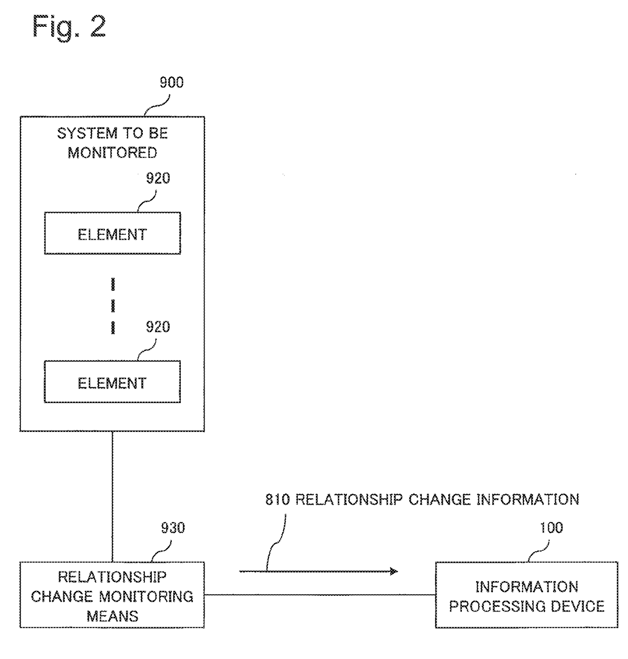
[0044]FIG. 2 is a block diagram illustrating the configuration of an information processing system including the information processing device 100, a system to be monitored (to be also simply referred to as a “system” hereinafter) 900, and a relationship change monitoring means 930.

[0045]===System to be Monitored 900===

[0046]The system to be monitored 900 includes a plurality of ele...

second exemplary embodiment

[0142]A second exemplary embodiment of the present invention will be described in detail below with reference to the drawings. A description of details which are the same as in the foregoing description will be omitted hereinafter within the range in which an explanation of the present exemplary embodiment does not become unclear.

[0143]FIG. 13 is a block diagram illustrating the configuration of an information processing device 200 according to the second exemplary embodiment of the present invention.

[0144]The information processing device 200 in the present exemplary embodiment is different from the information processing device 100 in the first exemplary embodiment in that the former includes an error detection unit 230 in place of the error detection unit 130, as illustrated in FIG. 13.

[0145]===Error Detection Unit 230===

[0146]The error detection unit 230 calculates an error level indicating the degree of deviation of the state graph 820 from the normal model 830, associated with...

third exemplary embodiment

[0152]A third exemplary embodiment of the present invention will be described in detail below with reference to the drawings. A description of details which are the same as in the foregoing description will be omitted hereinafter within the range in which an explanation of the present exemplary embodiment does not become unclear.

[0153]FIG. 15 is a block diagram illustrating the configuration of an information processing device 300 according to the third exemplary embodiment of the present invention.

[0154]The information processing device 300 in the present exemplary embodiment is different from the information processing device 100 in the first exemplary embodiment in that the former includes an error detection unit 330 in place of the error detection unit 130, as illustrated in FIG. 15.

[0155]===Error Detection Unit 330===

[0156]The error detection unit 330 outputs error information 840 including information indicating a vertex (element 920) and a side (a relationship between element...


PUM


Abstract

The present invention provides an information processing device that improves the detectability of system errors. This information processing device includes: a means that generates a state graph based on relationship change information indicating a change in the relationship between a plurality of elements included in a system, the state graph having the elements as the vertices thereof and the relationship between the elements as the sides thereof; a means that generates a normal model having the state graph as a set of conditions to be fulfilled during normal system operation, based on the relationship change information; and a means that detects system errors and outputs error information indicating detected errors, based on the state graph and the normal model.

Description

TECHNICAL FIELD[0001]The present invention relates to a technique for detecting system errors.BACKGROUND ART[0002]Various related-art techniques are known to detect system errors.[0003]For example, PTL 1 discloses a process monitoring device. The process monitoring device disclosed in PTL 1 operates in the following way.[0004]First, the process monitoring device extracts an attention-requiring process based on static attributes for the process. Examples of the static attributes include a process name, a manufacturer's name of a program for implementing the process, the program (software) name, a version, a name of a parent process that activates the process, and a process size. The process monitoring device extracts a relevant process as the attention-requiring process when current static attributes are different from past static attributes. The process monitoring device extracts the relevant process as the attention-requiring process when the past static attributes are unavailable....

Claims


Application Information

Patent Timeline
IPC IPC(8): G06F11/07G06F11/34G06F11/30
CPCG06F11/0787G06F11/302G06F11/3447G06F11/0772G06F11/079G06F11/0751G06F11/3086G06F11/3079G06F11/0718H04L41/0677H04L41/0631G06F11/3017G06F2201/81
Inventor NOMURA, TAKASHIKIDA, KOJIKAMIMURA, JUNPEISAKAE, YOSHIAKIKATSUDA, ETSUKOISOYAMA, KAZUHIKOYAMASAKI, KENTAROKOBAYASHI, YUJI
Owner NEC CORP
Why Eureka
Try Eureka