
Method and device for generating an optimum vertical path intended to be followed by an aircraft

a technology of vertical path and optimum path, which is applied in the direction of traffic control system, navigation instruments, instruments, etc., can solve the problems of high workload of crew, overshooting of the target point, and mismanagement of the energy of the target point by the aircraft,

Active Publication Date: 2017-05-11
AIRBUS OPERATIONS (SAS)
View PDF7 Cites 27 Cited by
  • Summary
  • Abstract
  • Description
  • Claims
  • Application Information

AI Technical Summary

Benefits of technology

The patent is about a device that is free from collisions with other obstacles, even if they are moving.

Problems solved by technology

In some situations where the aircraft has been diverted from its reference path, for example for traffic control reasons, the combination of this energy management and modification of the flight plan, which necessitates multiple interactions with the systems of the aircraft, generates a high workload for the crew.
Also, it can happen that the pilot of an aircraft seeking to arrive at a target point mismanages the energy of the aircraft and overshoots that target point, for example arriving at the target point too soon or at too great a height.
In the situation where the target point in the approach phase is a so-called stabilization point, the aircraft must then perform a go-around before landing, which wastes time.

Method used


Image

  • Method and device for generating an optimum vertical path intended to be followed by an aircraft
  • Method and device for generating an optimum vertical path intended to be followed by an aircraft
  • Method and device for generating an optimum vertical path intended to be followed by an aircraft

Examples


Embodiment Construction

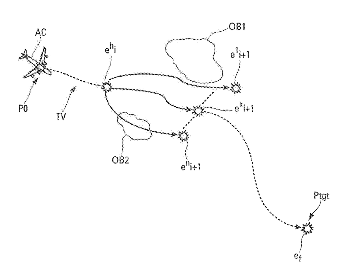
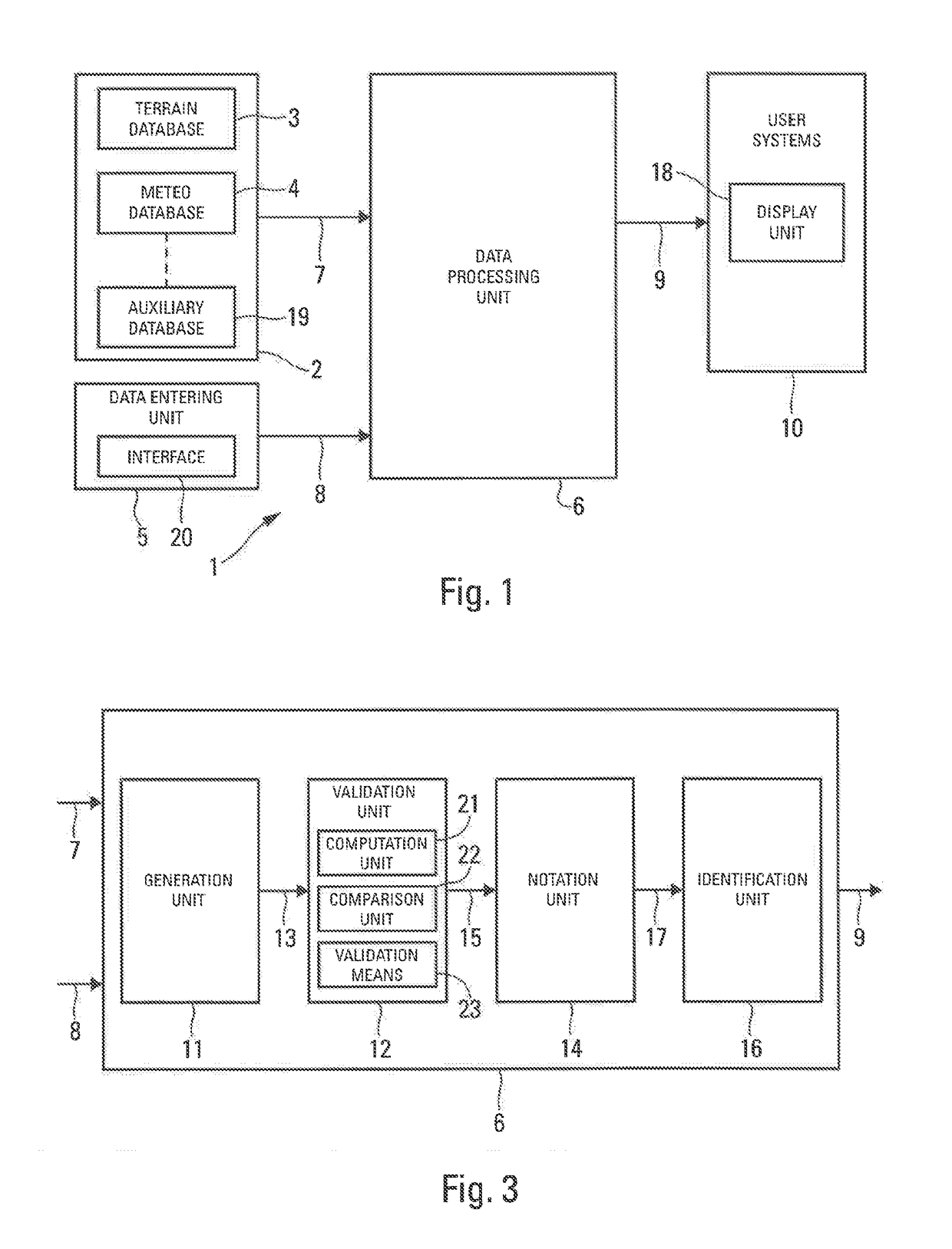
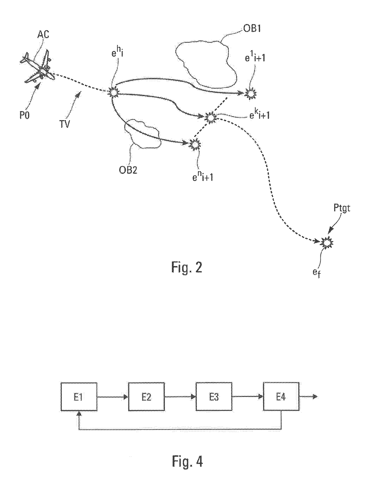
[0074]The device 1 used to illustrate the invention and represented diagrammatically in FIG. 1 has the object of constructing at least one vertical path TV of a flight path intended to be followed by an aircraft AC (FIG. 2), in particular a transport aircraft, in an environment liable to contain obstacles OB1 and OB2 (notably moving obstacles).

[0075]The flight path comprises a lateral (or horizontal) path that is defined in a horizontal plane and a vertical path that is defined in a vertical plane. The flight path connects a current point P0 (corresponding to the current position of the aircraft AC) at which the aircraft AC has a so-called current state to a target point Ptgt at which the aircraft AC has a so-called target state, as represented in FIG. 2.

[0076]A state comprises a point in space, for example P0, defined by its altitude and its horizontal position and one or more flight parameters of the aircraft. The flight parameter or parameters that are taken into account preferab...


PUM


Abstract

A method and device for generating an optimum vertical path intended to be followed by an aircraft. The device comprises at least one database relating to fixed and moving obstacles, a data entering unit, a data processing unit implementing iterative processing to generate an optimum vertical path between an initial state and a final state as a function of flight strategies, that optimum vertical path being generated in such a manner as to be free of any collision with surrounding obstacles and to conform to energy constraints, and a data transmission link for transmitting that optimum vertical path to at least one user system.

Description

CROSS-REFERENCES TO RELATED APPLICATIONS[0001]This application claims the benefit of the French patent application No. 1560600 filed on Nov. 5, 2015, the entire disclosures of which are incorporated herein by way of reference.BACKGROUND OF THE INVENTION[0002]The present invention concerns a method and a device for generating at least one optimum vertical path of a flight path intended to be followed by an aircraft, in particular a transport aircraft.[0003]An object of the present invention is more particularly to generate using onboard means and, in real time, an optimized path that is flyable in constrained dynamic environments, that is to say, in environments that are liable to contain objects (or obstacles) which the aircraft must be prevented from colliding with and notably mobile objects such as areas of meteorological disturbance, for example storm areas, or other aircraft.[0004]The present invention applies more particularly, although not exclusively, to approach paths during...

Claims


Application Information

Patent Timeline
IPC IPC(8): G08G5/02G08G5/00G08G5/04
CPCG08G5/025G08G5/0047G08G5/045G01C21/20G01C23/00G08G5/0021G08G5/0034
Inventor MERE, JEAN-CLAUDE
Owner AIRBUS OPERATIONS (SAS)
Learn More