Electric Work Vehicle, Battery Pack for Electric Work Vehicle and Contactless Charging System

Active Publication Date: 2017-05-18
KUBOTA LTD
View PDF1 Cites 10 Cited by
  • Summary
  • Abstract
  • Description
  • Claims
  • Application Information

AI Technical Summary

Benefits of technology

[0029]In a preferred embodiment of an electric mower in which a contactless charging system is incorporated, a mower unit hangs down elevatably at a front portion of the vehicle body frame, and an electric motor unit configured to drive the rear wheels using power supplied from the battery pack via a motor power supply circuit portion is arranged forward of an axle center of the rear wheels, between the rear wheels. With this configuration, with the mower unit and the electric motor unit, it is possible to solve the problem in which the center of gravity of the vehicle body is located rearward in the vehicle body and the vehicle body balance deteriorates due to the battery pack being arranged on the rear portion of the vehicle body frame.
[0030]Fu

Problems solved by technology

However, in a work vehicle that travels while performing work, as with a mower, a rice transplanter, a tractor, or the like, the surrounding environment for work travel is worse compared to the surrounding environment of an automobile or the like, and if cooling air is taken in from the surroundings, waste such as cut grass or straw tends to be mixed in with the cooling air, which causes the problem of clogging of the cooling air passage.
Accordingly, the case structure in which a mechanism for transmitting the power from the motors to the rear wheels is mounted has a rather complicated shape, and causes an increase in cost.
Furthermore, since

Method used


Image

  • Electric Work Vehicle, Battery Pack for Electric Work Vehicle and Contactless Charging System
  • Electric Work Vehicle, Battery Pack for Electric Work Vehicle and Contactless Charging System
  • Electric Work Vehicle, Battery Pack for Electric Work Vehicle and Contactless Charging System

Examples


first embodiment

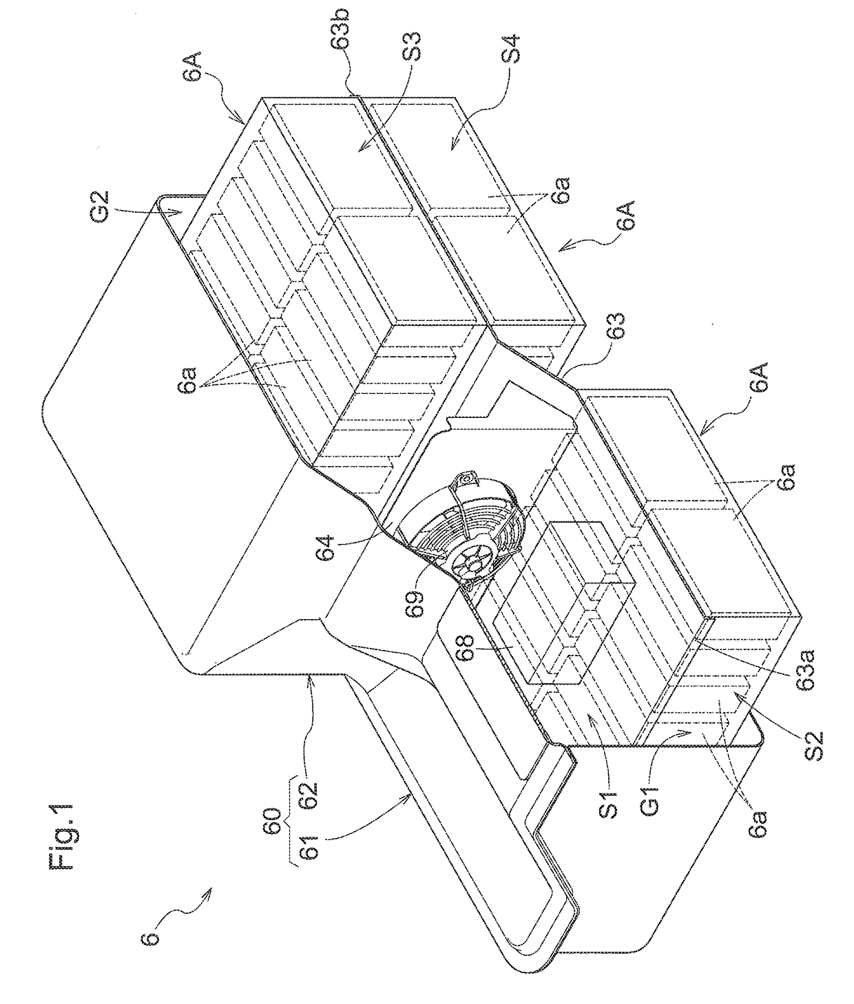
[0050]Prior to describing specific embodiments of the battery pack relating to the present invention, a basic structure of the battery pack mounted in the electric work vehicle will be described with reference to FIG. 1, and a basic arrangement of the battery pack at the time of mounting such a battery pack in the electric work vehicle will be described with reference to FIGS. 2 and 3.

[0051]A battery pack 6 as shown in FIG. 1 includes a battery case 60, a horizontal partitioning wall 63, a battery electric unit 68 (a group of electric devices / accessories related to a battery; the collective nomination will be simply referred to as “electric unit 68” also) and multiple battery modules 6A. The battery case 60 is a sealed case including a front case portion 61 and a rear case portion 62. Note that in FIG. 1, the left side is defined as the front side (forward), and the right side is defined as the rear side (rearward). The front case portion 61 and the rear case portion 62 are not indi...

second embodiment

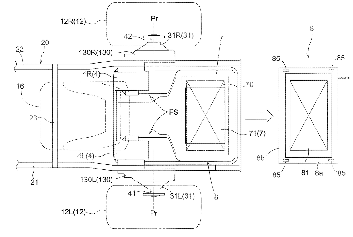
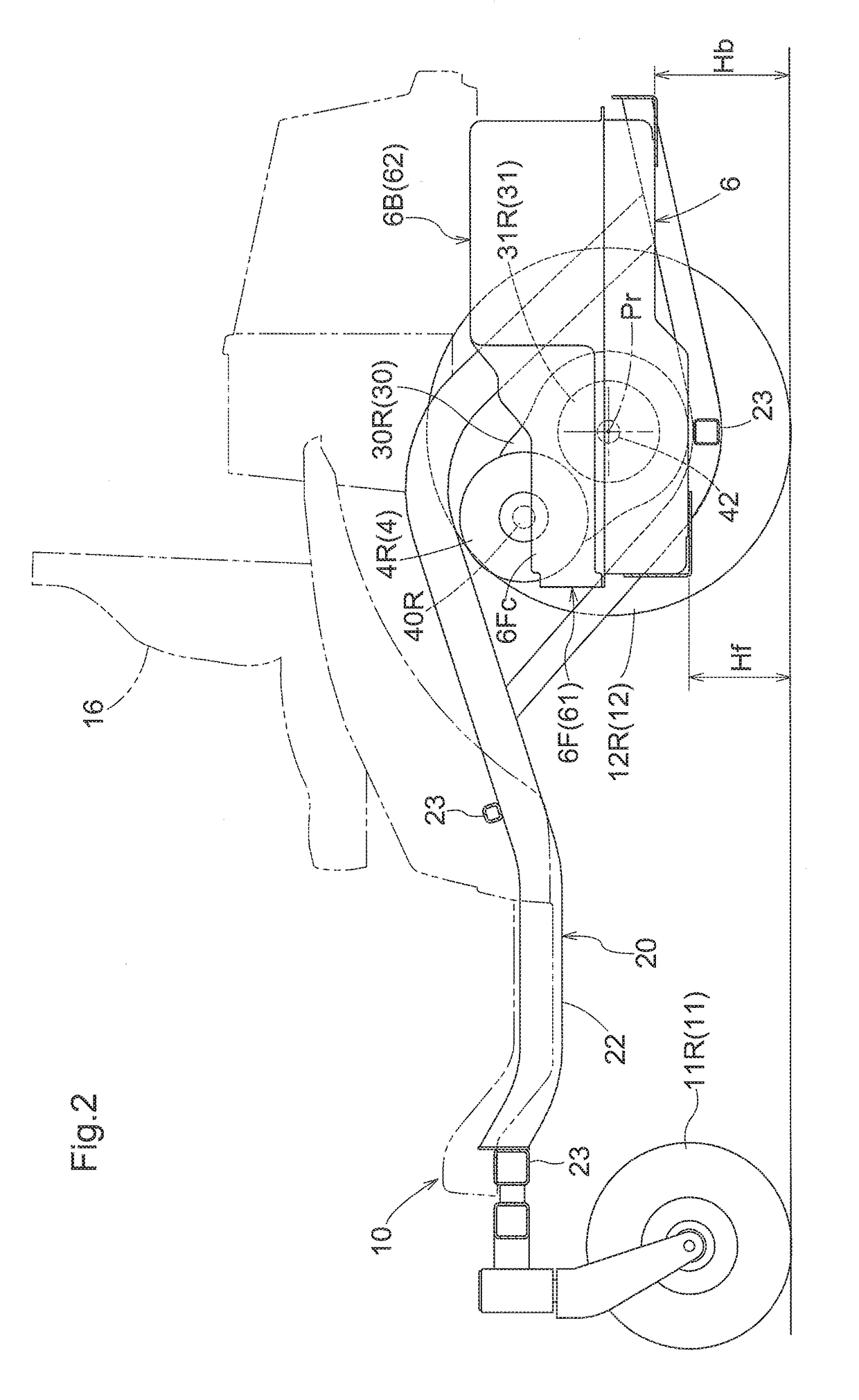
[0077]A basic configuration of an electric work vehicle in which a contactless charging system is incorporated will be described with reference to FIGS. 10 and 11.

[0078]The electric work vehicle includes a vehicle body frame 20 that includes a left frame 21 and a right frame 22 that extend in the vehicle body front-rear direction with an interval therebetween in the vehicle body lateral direction, and at least one crossbeam 23 that connects the left frame 21 and the right frame 22. A left front wheel 11L and a right front wheel 11R that constitute a front wheel unit 11 are arranged at the front portion of the vehicle body frame 20. A left rear wheel 12L and a right rear wheel 12R that constitute a rear wheel unit 12 are arranged rearward of the center of the vehicle body frame 20. Hereinafter, if there is no particular need to make a distinction, the left front wheel 11L and the right front wheel 11R will be referred to collectively as “front wheel unit 11”, and the left rear wheel ...


PUM


Abstract

An electric work vehicle includes: a battery pack that is arranged between a left rear wheel arranged outside of a left frame and a right rear wheel arranged outside of a right frame, the front end of the battery pack being located forward of an axle center of a rear wheel unit; a left motor that is arranged above the battery pack, in the periphery of the left rear wheel, receives a supply of power from the battery pack, and transmits rotational power to the left rear wheel; and a right motor that is arranged above the battery pack, in the periphery of the right rear wheel, receives a supply of power from the battery pack, and transmits rotational power to the right rear wheel.

Description

CROSS-REFERENCE TO RELATED APPLICATIONS[0001]This application claims priority to Japanese Patent Application Nos. 2015-224090 and 2015-224091, both filed Nov. 16, 2015, and Japanese Patent Application No. 2016-065374 filed Mar. 29, 2016, the disclosures of which are hereby incorporated in their entirety by reference.BACKGROUND OF THE INVENTION[0002]Field of the Invention[0003]The present invention relates to an electric work vehicle such as an electric mower, a battery pack for an electric work vehicle, and a contactless charging system.[0004]Description of Related ArtFirst Related Art[0005]In the field of passenger vehicles, electric vehicles that travel using the rotational force of an electric motor have started to become widespread. In such a case, a battery is mounted in the vehicle as the power source of the electric motor. The battery temperature needs to be kept at a suitable temperature in order to maintain the performance of the battery, and therefore a cooling structure i...

Claims


Application Information

Patent Timeline
IPC IPC(8): B60K1/04B60K7/00A01D69/02A01D34/78A01D34/82B60L11/18B60K17/04B60L50/64
CPCB60K1/04A01D2101/00B60L11/1877B60L11/182B60L11/1824B60K7/0007B60K17/043A01D34/78A01D34/82A01D69/02B60L2200/40B60L2220/42B60L2220/46B60K2001/0416B60K2001/005B60Y2200/223B60Y2300/91B60Y2304/01B60Y2400/112A01D34/66B60L11/1874B60K2007/0053B60K2007/0061H01M10/625B60K2007/0046H01M10/6563H01M10/6551B60L58/26B60L50/66B60L53/305B60L53/302B60L53/122B60L53/126Y02T10/64Y02T90/16H01M50/249B60L50/64Y02T90/12Y02T10/7072Y02T90/14Y02T10/70
Inventor ITO, HIROKAZUKOIKE, KAZUOMANJI, YASUHIRO
Owner KUBOTA LTD
Why Eureka
Try Eureka