Disc Brake and Brake Pad Set

a technology of disc brakes and brake pads, applied in the direction of axially engaging brakes, brake types, braking elements, etc., can solve the problem of even wear on the brake pads, and achieve the effect of preventing rotational movement of the brake pads and compact design

Active Publication Date: 2017-05-18
BENDIKS SPAJSER FAUNDEJSHN BREJK LLK +1
View PDF4 Cites 6 Cited by
  • Summary
  • Abstract
  • Description
  • Claims
  • Application Information

AI Technical Summary

Benefits of technology

[0057]In another embodiment, the spring arm of the at least one pad retaining spring is fastened to the base plate by a curved connecting section. This yields the advantage of creating an additional spring force.
[0058]In addition, the curved connecting section can communicate with the shape of a contact surface of the protrusion, so that an advantageous and compact support of the connecting section in the uninstalled state of the brake pad is possible.
[0059]In yet another embodiment variant, the at least one pad retaining spring may have at least one supporting section, which is mounted on the base plate opposite the spring arm and has on its bottom side at least one supporting section, which is supported on the top side of the pad rear plate. This makes it possible to prevent a rotational movement of the pad retaining spring about its mount on the protrusion.
[0060]In yet another embodiment, the at least one pad retaining spring may be provided with at least one slot. This yields the advantage that the different spring forces required for different application cases can be obtained. This may also take place due to the fact that the at least one pad retaining spring is provided with at least one reinforcing bead and / or at least one reinforcing rib. The reinforcing bead and / or reinforcing rib may be used alone or in combination with the at least one slot.
[0061]The at least one pressure section protrudes laterally away from the pad rear plate at one end of the top side of the pad rear plate and thus permits a compact design.
[0062]It is advantageous here that the at least one pressure section is supported on the at least one brake carrier horn of the pad slot of the brake carrier, thereby creating a tensile force acting on the brake pad.

Problems solved by technology

In the case of disc brakes, in particular disc brakes having only one force-introducing element, uneven wear may occur on the brake pads due to the design.

Method used


Image

  • Disc Brake and Brake Pad Set
  • Disc Brake and Brake Pad Set
  • Disc Brake and Brake Pad Set

Examples


first embodiment

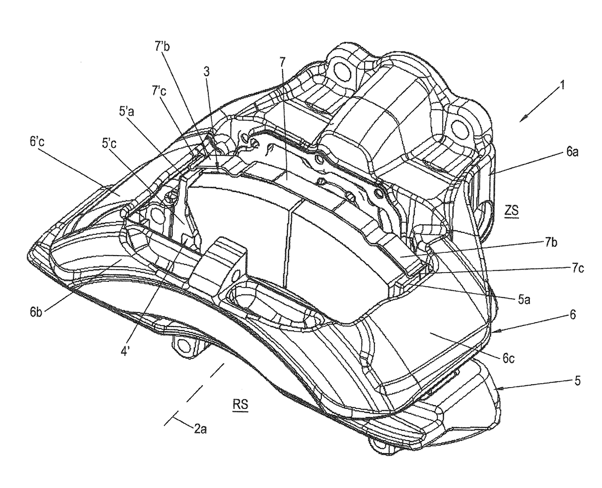
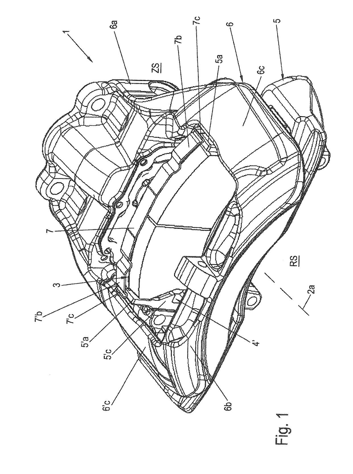
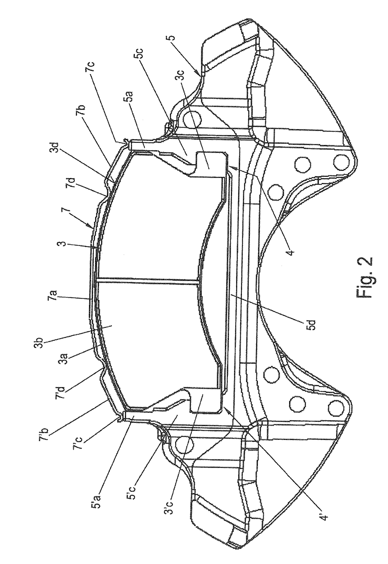
[0092]FIG. 1 shows a schematic perspective view of a disc brake 1 according to the invention, for example, a pneumatic disc brake 1. Schematic partial views of a brake carrier 5 of the disc brake 1 according to the invention, as shown in FIG. 1, can be seen in FIGS. 2 through 4 with a brake pad 3 according to the invention. FIG. 1 does not show a brake disc 2 for the sake of simplicity, but it can be imagined easily by reference to FIG. 9. FIG. 2 shows a top view of a friction lining 3b of the brake pad 3 in a brake carrier 5. FIG. 3 shows forces 11, 12 acting on brake pad 3. FIG. 4 shows an enlarged diagram of one side of the brake pad 3 engaged with a brake carrier horn 5′a.

[0093]The disc brake 1 is part of the brake system of a vehicle, for example, in particular a commercial vehicle, and comprises the brake disc 2 with an axis of rotation 2a of the brake disc and two brake pads 3 arranged on both sides of the brake disc 2. Of the two brake pads 3, only one so-called clamping-si...

third embodiment

[0141]In this third embodiment, the pad retaining spring 7 comprises a central section 7a, arms 7b, 7′b, pressure sections 7c, 7′c and intermediate sections 7e, 7′e.

[0142]The central section 7a is provided with a slot 7f running in the longitudinal direction of the pad retaining spring 7 to receive a section of a fastening element 20. The slot 7f does not run in an imaginary central line of the pad retaining spring 7 but instead runs with an offset in the direction toward the friction lining 3b and parallel to the imaginary central line of the pad retaining spring 7. This imaginary central line runs in the longitudinal direction of the pad retaining spring 7.

[0143]In contrast with the first embodiment, the length of the central section 7a corresponds to approximately one-half the length of the central section 7a of the pad retaining spring 7 of the first embodiment.

[0144]An arm 7b, Tb is mounted at each end of the central section 7a. The arms 7b, 7′b are much longer in contrast wit...

fifth embodiment

[0163]FIG. 21 shows a schematic partial view of the disc brake 1 according to the invention from the direction of the clamping side ZS toward the activating side 3j of the brake pad 3 on the clamping side.

[0164]FIGS. 22-25 show enlarged schematic partial views of the fifth embodiment of the disc brake according to the invention, as shown in FIG. 21. Thus, FIG. 22 shows a central upper section of the pad rear plate 3a with a retainer for the pad retaining spring 7. FIG. 23 shows one end on the inlet side of the pad retaining spring 7 like that in FIG. 4, for example. Finally, FIG. 24 shows the end according to FIG. 23 on the inlet side in a view from the top.

[0165]In this fifth embodiment, the components of the disc brake 1 are the same as those in the third embodiment (FIG. 12) except for the brake pad 3 and the pad retaining spring 7. Therefore, only the differences in the brake pad 3 and the respective pad retaining spring 7 are discussed further here.

[0166]In contrast with the fi...


PUM


Abstract

A disc brake for a vehicle, in particular for a commercial vehicle, includes a brake carrier which receives at least two brake pads in respective clamping side and rear side pad slots, with the at least one brake pad on the clamping side being held in its pad slot in a form-fitting manner. The at least one brake pad on the clamping side is provided with at least one pad retaining spring which is supported at least on a brake carrier horn of the pad slot of the brake carrier. The at least one clamping spring exerts a tensile force acting radially outward on the brake pad. A brake pad set for the disc brake is also provided.

Description

CROSS REFERENCE TO RELATED APPLICATIONS[0001]This application is a Continuation-in-Part of U.S. application Ser. Nos. 14 / 939,735 and 14 / 939,748, both filed Nov. 12, 2015, the entire disclosures of which are herein expressly incorporated by reference.BACKGROUND AND SUMMARY OF THE INVENTION[0002]The present invention relates to a disc brake according to the preamble of claim 1. The invention also relates to a brake pad set for a disc brake.[0003]Such disc brakes are used in commercial vehicles in particular and are often provided with pneumatic actuation. One embodiment of the brake caliper of such a disc brake is designed as a disc caliper and is used in a tight installation space, for example.[0004]The brake caliper is usually connected to the so-called brake carrier by two bearing spars, which are designed as fixed bearings and loose bearings. The brake pads of the disc brakes are guided displaceably in the brake carrier and are held in a spring-loaded connection by pad retainer br...

Claims


Application Information

Patent Timeline
Patent Type & Authority Applications(United States)
IPC IPC(8): F16D65/097
CPCF16D55/225F16D65/0974F16D55/2255F16D65/0056F16D65/0068F16D2065/026
Inventor SCHROPP, JOSEFSCHOENAUER, MANFREDPAHLE, WOLFGANGBARTEL, MARKUSFISCHL, TOBIASBAUMGARTNER, JOHANNPETSCHKE, ANDREASBOHMANN, MARKUSLANTZ, RICHARDTEKESKY, ROBERT
Owner BENDIKS SPAJSER FAUNDEJSHN BREJK LLK
Why Eureka
Try Eureka