
Gas Permeable Internal Floating Piston

Inactive Publication Date: 2017-05-18
BANDY RONALD SCOTT
View PDF7 Cites 3 Cited by
  • Summary
  • Abstract
  • Description
  • Claims
  • Application Information

AI Technical Summary

Benefits of technology

The patent improves the dampening properties of an air shock by keeping the oil and gas separate during operation. It also helps to make the air shock shorter without affecting its spring rate.

Problems solved by technology

The emulsion is well known in the art and is considered to provide unpredictable dampening properties in a shock absorber, which in turn, lead to unpredictable handling characteristics for the vehicle.
The deficiency of the emulsion lies in the mixing of the oil with the gas.
Such an addition process is not realistic for the multiple stage air shock.
However, one of the ends of one interconnecting component travels into another interconnecting component during the operation of the air shock, and therefore, is not available for receiving a check valve.

Method used


Image

  • Gas Permeable Internal Floating Piston
  • Gas Permeable Internal Floating Piston
  • Gas Permeable Internal Floating Piston

Examples


Embodiment Construction

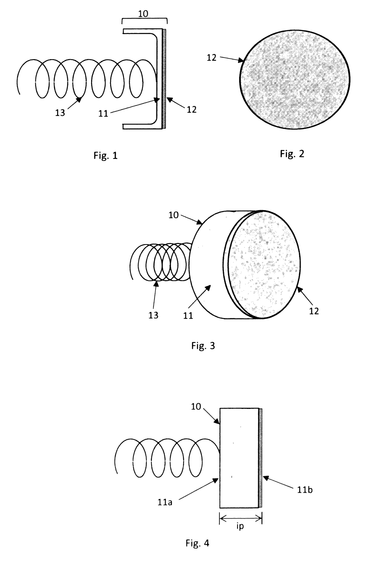
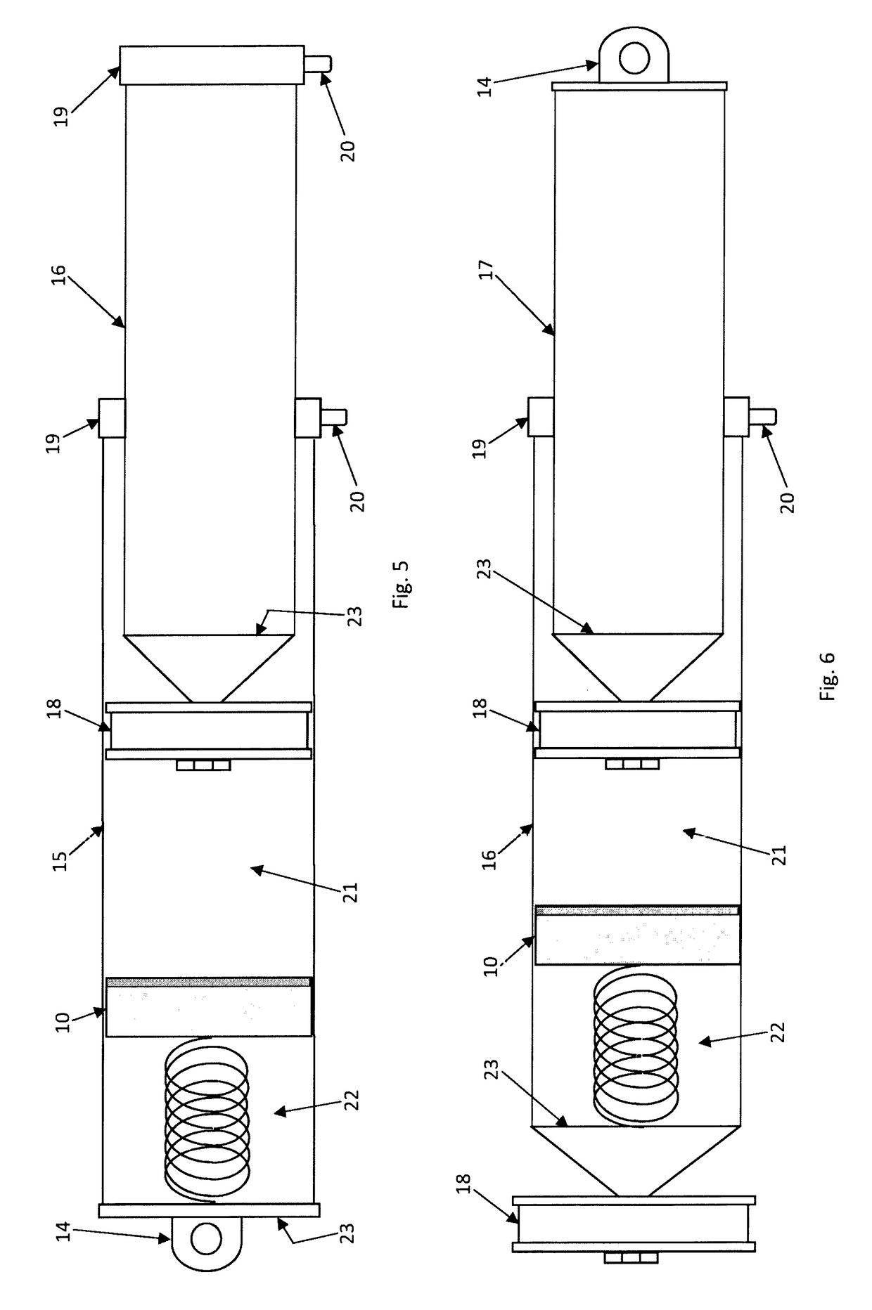
[0111]Described below is a gas permeable internal floating piston specifically designed for installation on the multiple stage air shock. The multiple stage air shock is disclosed in patent application Ser. No. 13 / 854,055 whereby a process for constructing the multiple stage air shock is disclosed in patent application Ser. No. 14 / 935,423. The internal floating piston features a gas permeable membrane that has a slow rate of permeation whereby the permeability serves to separate the oil from the gas while the slow rate of permeation permits the internal floating piston to move in conjunction with the shaft during the operation of the air shock. To facilitate understanding of the present invention, the multiple stage air shock is described; and then exemplified with the four stage air shock.

[0112]Referring to FIGS. 1-4, the internal floating piston 10 is illustrated in detail. The internal floating piston 10 has a composite construction that includes a cup 11 and gas permeable membra...


PUM


Abstract

Disclosed herein is a novel gas permeable internal floating piston specifically designed for installation in the multiple stage air shock whereby the multiple stage air shock is covered in patent application Nos. 13 / 854,055 and 14 / 935,423. The multiple stage air shock includes a mixture of oil and gas whereby the mixture provides the shock with emulsion dampening properties. The gas permeable internal floating piston operates by separating the oil from the gas thereby improving the dampening properties of the shock. The permeability of the internal floating piston is based on a membrane that allows the gas but not the oil to pass through the structure of the internal floating piston. The mechanism of the permeability is governed by the creation of a pressure differential across the structure of the internal floating piston, the creation effected with a spring. The membrane features a slow rate of permeation thereby ensuring that the internal floating piston moves in conjunction with the shaft during the operation of the shock.

Description

CROSS-REFERENCE TO RELATED APPLICATIONS[0001]This application represents a novel internal floating piston that is designed exclusively for the multiple stage air shock. The multiple stage air shock is covered in U.S. patent application Ser. No. 13 / 854,055 and 14 / 935,423.STATEMENT REGARDING FEDERALLY SPONSORED RESEARCH OR DEVELOPMENT[0002]Not Applicable[0003]REFERENCE TO SEQUENCE LISTING, A TABLE OR A COMPUTER PROGRAM LISTING COMPACT DISC APPENDIX[0004]Not ApplicableBACKGROUND OF THE INVENTION[0005]Disclosed in patent application Ser. No. 13 / 854,055 is the multiple stage air shock; and, disclosed in patent application Ser. No. 14 / 935,423 is a process for constructing the multiple stage air shock whereby the process introduces several features including the determination of various lengths and spring rates that are absent in the art. The multiple stage air shock possesses both dampening and suspension spring capabilities whereby the dampening capability is based on an emulsion compris...

Claims


Application Information

Patent Timeline
IPC IPC(8): F16F9/06
CPCF16F9/061F16F9/067
Inventor BANDY, RONALD SCOTT
Owner BANDY RONALD SCOTT
Learn More