
Digital Approach to the Removal of AC Parasitics for Impedance Measurements

a digital approach and impedance measurement technology, applied in the field of instrumentation, can solve problems such as current loss

Active Publication Date: 2017-05-18
NATIONAL INSTRUMENTS
View PDF4 Cites 5 Cited by
  • Summary
  • Abstract
  • Description
  • Claims
  • Application Information

AI Technical Summary

Benefits of technology

The patent describes an improved measurement system that can accurately measure low-level currents. The system uses a source measure unit (SMU) that provides a controlled DC voltage with precision current limiting and a controlled 0V (zero Volt) DC voltage at the measurement terminal. The system also includes control circuits that generate control signals with programmable frequency and continuously variable phase and amplitude to control the voltage at the measurement terminal. The system can measure the voltage, current, and voltage at the second device terminal using off-the-shelf pipelined analog-to-digital converters (ADCs) and a Fourier transform to provide both amplitude and relative phase measurement. The system can adjust the voltage to a specified value within a specified range of a nominal value by adjusting the phase and amplitude of the control signals. The system can also include two control loops to adjust the control signals based on measurement values. Overall, the system provides accurate and reliable measurements of low-level currents.

Problems solved by technology

However, the accuracy of many measurements, for example low-level current measurements, may still be adversely affected by parasitics leading to current loss.

Method used


Image

  • Digital Approach to the Removal of AC Parasitics for Impedance Measurements
  • Digital Approach to the Removal of AC Parasitics for Impedance Measurements
  • Digital Approach to the Removal of AC Parasitics for Impedance Measurements

Examples


Embodiment Construction

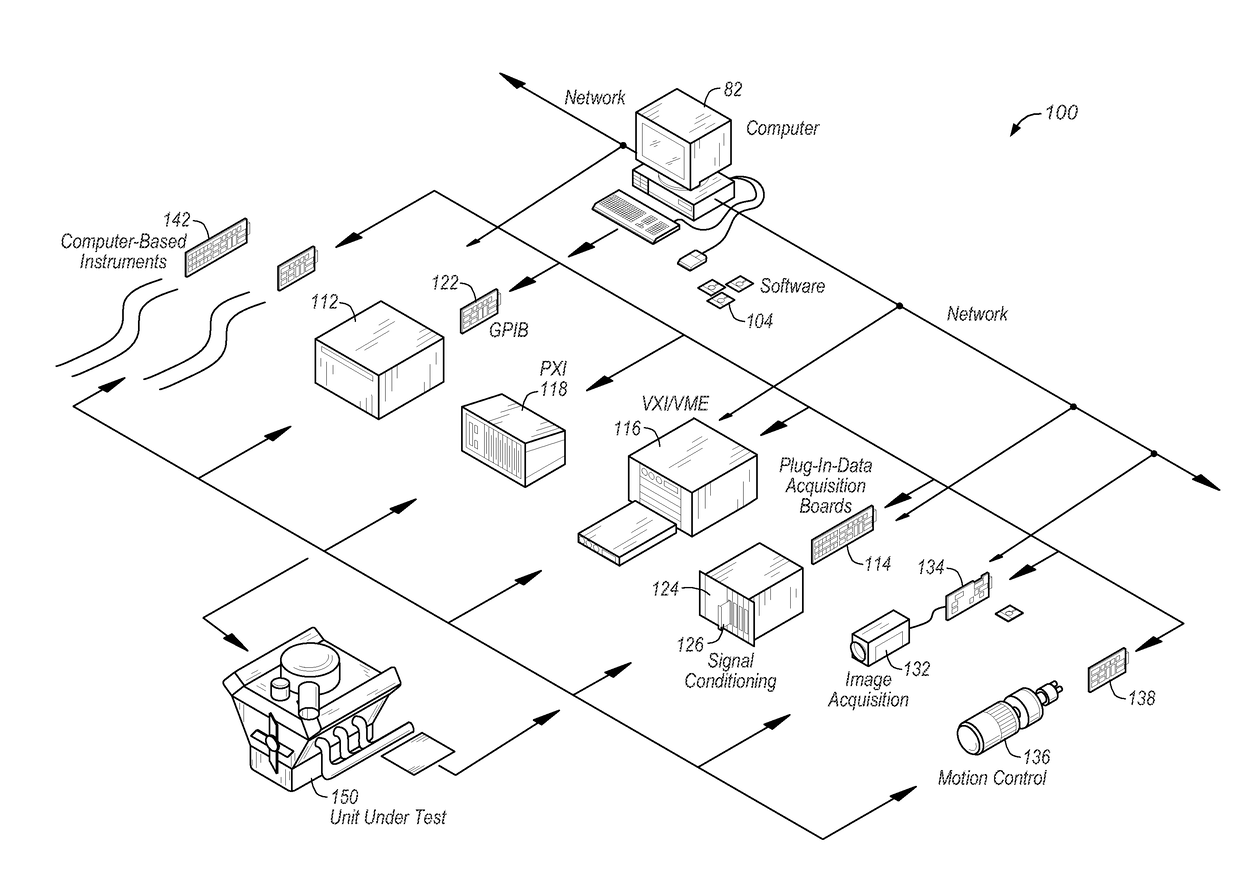
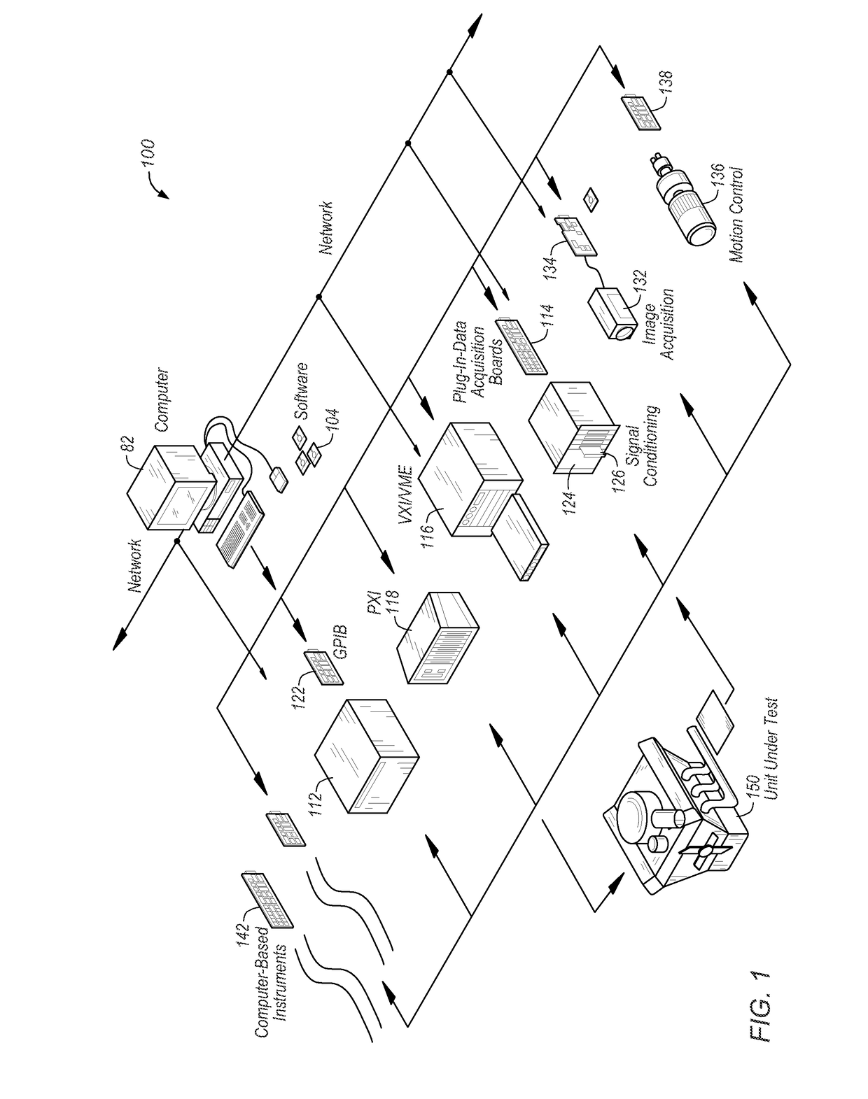
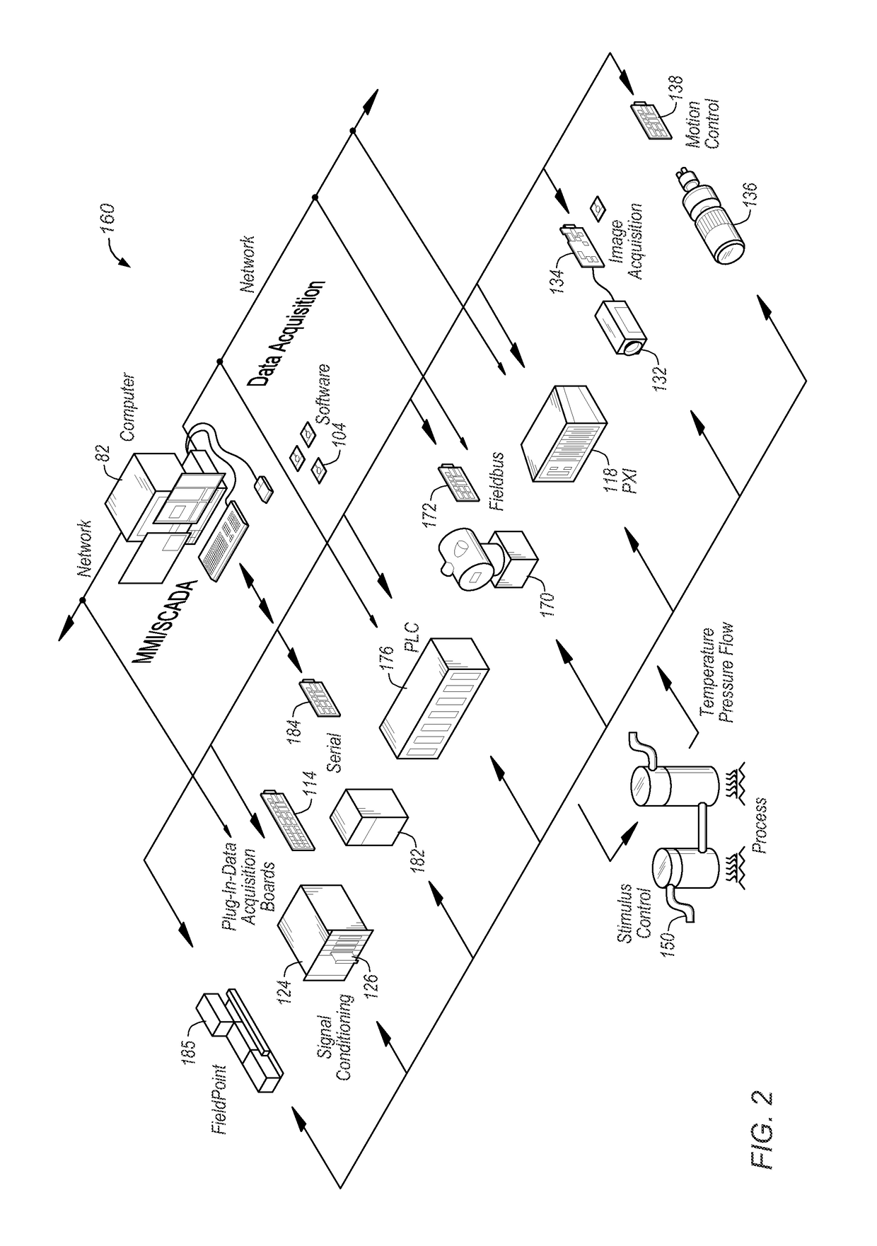
[0026]Embodiments of improved source measure units (SMUs) and / or measurement circuits described herein may be used in systems configured to perform test and / or measurement functions, to control and / or model instrumentation or industrial automation hardware, or to model and simulate functions, e.g., modeling or simulating a device or product being developed or tested, etc. More specifically, they may be used in various instances where accurate measurements are required, and more specifically, where accurate low-level current measurements may be required. However, it is noted that various embodiments may equally be used for a variety of applications, and such applications are not intended to be limited to those enumerated above. In other words, applications discussed in the present description are exemplary only, and various embodiments of improved source measure units (SMUs) with increased measurement accuracy may be used in any of various types of systems.

[0027]FIG. 1 illustrates an...


PUM


Abstract

An improved measurement system may include a source measure unit (SMU) capable of performing accurate low-level current measurements. Based on an SMU design that provides a controlled DC voltage source with precision current limiting and a controlled 0V (zero Volt) DC at the measurement terminal, an AC design may be implemented to establish the same (or very similar) conditions over a specified frequency range. Instead of controlling each digital-to-analog converter (DAC) at respective source terminals of the SMU as a respective DC output, each DAC may be controlled as a respective function generator with programmable frequency and continuously variable phase and amplitude. Off-the-shelf pipelined analog-to-digital converters (ADCs) may be used to monitor voltage, current and the voltage at the measurement terminal, and a Fourier transform may be used to obtain both the amplitude and relative phase measurements to be provided to respective control loops.

Description

FIELD OF THE INVENTION[0001]The present invention relates to the field of instrumentation, and more particularly to improved removal of AC parasitics and cabling / connectivity parasitics in measurement instruments.DESCRIPTION OF THE RELATED ART[0002]In many industrial applications (and others), instruments collect data or information from an environment or unit under test (UUT), and may also analyze and process acquired data. Some instruments provide test stimuli to a UUT. Examples of instruments include oscilloscopes, digital multimeters, pressure sensors, arbitrary waveform generators, digital waveform generators, etc. The information that may be collected by respective instruments includes information describing voltage, resistance, distance, velocity, pressure, oscillation frequency, humidity, and / or temperature, among others. Computer-based instrumentation systems typically include transducers for capturing a physical phenomenon and generating a representative electrical signal,...

Claims


Application Information

Patent Timeline
IPC IPC(8): G01R31/28
CPCG01R31/2834G01R19/0092G01R19/0053G01R31/00
Inventor LINDELL, BLAKE A.REGIER, CHRISTOPHER G.LIMON, PABLO
Owner NATIONAL INSTRUMENTS
Learn More