Magnifying bottle cap assembly

a bottle cap and magnification technology, applied in the field of magnification end caps, can solve the problems of lack of reliability and durability of the magnifying cap itself, the failure of the magnification means for viewing the internal contents of the attached container with sealing properties, and the failure of the cap and bottle assembly to integrate the magnification means with the sealing properties of the attached container, so as to prevent the entry of air, improve the stability of the component elements, and prevent the effect of air entering

Inactive Publication Date: 2017-05-18
CRENKO THOMAS
View PDF3 Cites 5 Cited by
  • Summary
  • Abstract
  • Description
  • Claims
  • Application Information

AI Technical Summary

Benefits of technology

[0007]The present invention is a magnifying bottle cap assembly with improved stability of its component elements including a cap body, an integrated magnifying lens element, said lens element further comprising a lens with a radially extended periphery and standoff reinforcing elements arranged in a non-radial position thereto. The cap body is formed to further comprise top and bottom annular retaining rings for contacting and permanently retaining the radially extended periphery of the lens element and to full engage the circumference and at least partially engage the height of the standoff reinforcing elements. The magnifying cap assembly, when engaged with a container, effectuates a seal between the cap assembly and container thereby permitting secure storage of contents, such as medicines, biology samples, specimens and the like, within the container. The magnifying bottle cap assembly provides magnification of the contents of the container, as well as other benefits including stable storage of the contents of the container and the prevention of the entrance of air or liquid into the sealed container and the effects of the interaction of such fluids with the contents of the assembly.
[0008]Magnifying bottle assemblies with improved stability and permanence of an integrated magnifying element consistent with the teachings of the present disclosure, as described above and as further described herein, permit the stable storage of the contents of the bottle and cap assembly and permit one to view the contents of the bottle and cap assembly optically magnified.

Problems solved by technology

Prior art magnifying caps, or cap and bottle assemblies, have failed to integrate magnification means for viewing of the internal contents of the attached container with sealing properties sufficient to provide for stability of the container's contents and durability of the magnifying end cap itself.
Relatedly, those containers in the prior art that do include magnifying means, such as U.S. Pat. No. 5,760,975 to DiGiovanni or U.S. Pat. No. 8,844,722 to Wang, fail to direct and apply the forces between the cap and container components to stabilize and secure the magnifying means within the cap to ensure security of the components of the container and cap, or the seal between the cap and container.
This results in lack of reliability and durability of the magnifying cap itself and further prevents the designs of the prior art from achieving seals between the cap components or between the cap assembly and container portion sufficient to provide stable storage for the bottle's contents and protection of the contents from the deleterious effects of exposure to outside air, outside liquids, contaminants and the like.
These means, however, do not effect permanent and stable engagement of the magnifying lens with the retaining element.
These references, however, still fail to effect permanent engagement of the lens with the frame and also fail to adequately reduce stress upon the lens from shear forces.
U.S. Pat. No. 5,680,260 to Farcella, et al., and U.S. Pat. No. 7,289,282 to Matsushima similarly fail to achieve permanent engagement of the lens, and further, employ techniques that require the assembly of multiple pieces and risk breakage of the retaining members when the same are inserted into pre-defined recesses.

Method used


Image

  • Magnifying bottle cap assembly
  • Magnifying bottle cap assembly
  • Magnifying bottle cap assembly

Examples


Embodiment Construction

[0016]The invention of the present disclosure is described below with reference to certain embodiments. While these embodiments are set forth in order to provide a thorough and enabling description of the invention, these embodiments are not set forth with the intent to limit the scope of the disclosure. A person of skill in the art will understand that the invention may be practiced in numerous embodiments, of which those detailed here are merely examples. In order to allow for clarity of the disclosure of the claimed invention, structures and functions well known to those skilled in the art are not here disclosed. Those skilled in the art should also realize that equivalent magnifying bottle cap assemblies do not depart from the spirit and scope of the invention in its broadest form.

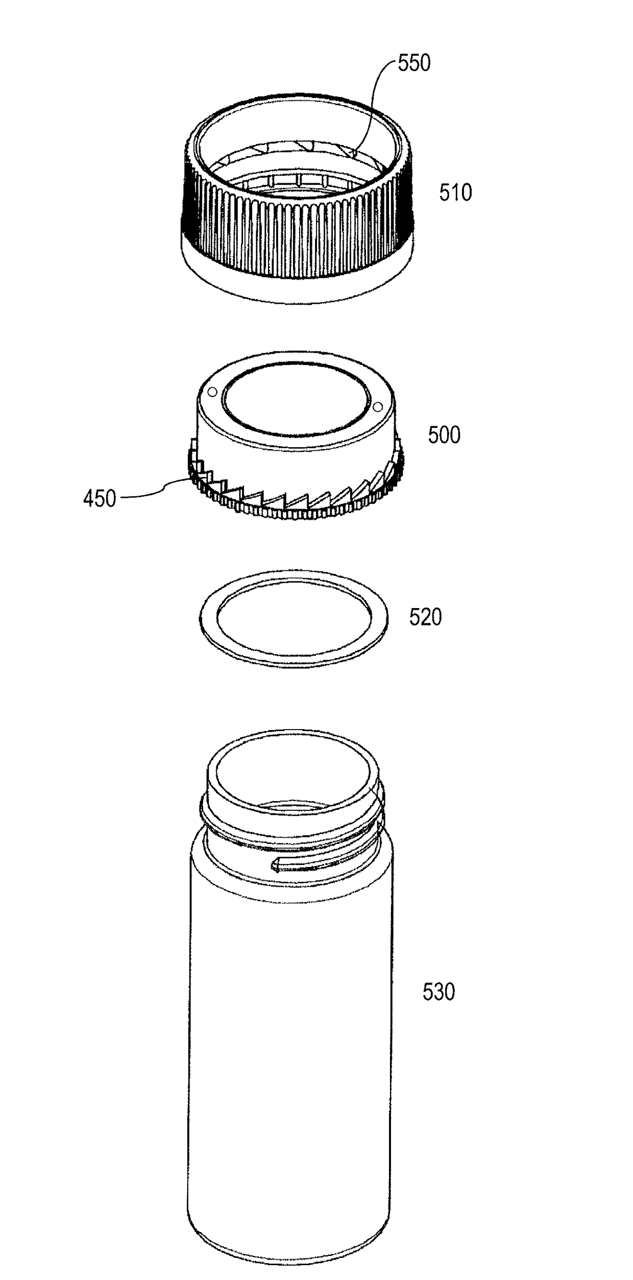
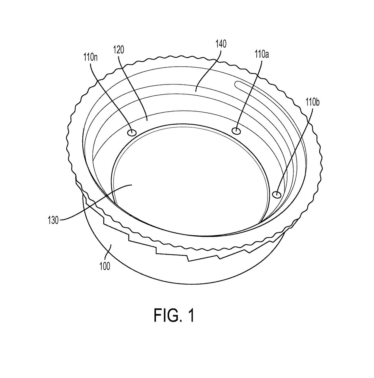
[0017]FIG. 1 depicts an exemplary embodiment of a magnifying bottle cap assembly according to the present invention, comprising a bottle cap body 100 formed to stably and permanently engage a magnifyin...


PUM


Abstract

A magnifying bottle cap assembly comprising a magnifying lens assembly. Said magnifying lens assembly comprising a magnifying lens with an integral radially extended periphery and a plurality of standoff reinforcing elements integral to said radially extended periphery, said standoff reinforcing elements arranged non-radially to the lateral plane of said radially extended periphery, a unitary cap body comprising an annular portion for engaging a bottle, said portion for engaging having an inner diameter less than or equal to the diameter of said magnifying lens assembly, a first annular retaining portion formed to mechanically engage the top of said magnifying lens assembly and to mechanically engage the perimeter of the standoff reinforcing elements integral to the top of said radially extended periphery, a second annular retaining portion formed to mechanically engage the bottom of said magnifying lens assembly and to mechanically engage the perimeter of the standoff reinforcing elements integral to the top of said radially extended periphery.

Description

RELATED U.S. APPLICATION[0001]The present application is a continuation-in-part of U.S. application Ser. No. 14 / 944,346.FIELD OF THE INVENTION[0002]The present invention relates generally to a magnification end cap and more particularly to a magnification end cap permitting a magnified view of the contents of a bottle and effecting stabilized, permanent engagement of the magnifying element of the magnification end cap with the body of the end cap.BACKGROUND[0003]The use of a magnification device is known in the prior art for combination with jars, bottles and other containers, such as medicine bottles: for example U.S. Pat. No. 5,760,975 to DiGiovanni and U.S. application Ser. No. 10 / 807,411 by Muir; and specimen containers: for example Nature-Watch Bug Viewer and HABA Terra Kids Beaker Magnifier.[0004]Prior art magnifying caps, or cap and bottle assemblies, have failed to integrate magnification means for viewing of the internal contents of the attached container with sealing prope...

Claims


Application Information

Patent Timeline
Patent Type & Authority Applications(United States)
IPC IPC(8): G02B27/02B65D41/00B65D51/24G02B7/02
CPCG02B27/027B65D51/24B65D41/00G02B7/026B65D51/245
Inventor CRENKO, THOMAS
Owner CRENKO THOMAS
Why Eureka
Try Eureka