Moving vehicle detection and analysis using low resolution remote sensing imagery

a remote sensing and vehicle detection technology, applied in image analysis, image enhancement, instruments, etc., can solve the problems of large satellite resources, high cost, and inability to obtain high-resolution aerial images, and achieve high spatial resolution images. , the effect of high spatial resolution

Active Publication Date: 2017-05-18
ORBITAL INSIGHT INC
View PDF13 Cites 46 Cited by
  • Summary
  • Abstract
  • Description
  • Claims
  • Application Information

AI Technical Summary

Problems solved by technology

Obtaining high resolution aerial images typically requires use of large, expensive satellites and results.
These satellites typically require a significant amount of resources.
For example, such satellites carry sophisticated and expensive equipment such as high spatial resolution cameras, expensive transponders, and advanced computers.
Other factors that contribute to the cost associated with expensive imaging satellites are the launch cost and maintenance.
Expensive high spatial resolution imaging satellites must be monitored from a ground facility,

Method used


Image

  • Moving vehicle detection and analysis using low resolution remote sensing imagery
  • Moving vehicle detection and analysis using low resolution remote sensing imagery
  • Moving vehicle detection and analysis using low resolution remote sensing imagery

Examples


example training

Sets For The Machine Learning Model

[0071]FIG. 5 illustrates example training sets 500 and 510 for the machine learning model 106 in the moving vehicle analysis system 101. Each training set includes the training images 401 and training labels 402 illustrated and described in FIG. 4. The positive training set 500 shown in FIG. 5 contains features 410 that have been determined to have the presence of moving vehicles. The positive training set 500 is a combined image from images taken at distinct times. The positive training set 500 includes two labeled pixel blobs 501 and 502. In one example, pixel blob 501 corresponds to the green spectral band and pixel blob 502 corresponds to the red spectral band. The positive training set 500 further includes a moving vehicle training label 503 used by the machine learning model training engine 203 to train the machine learning model 106 that the two pixel blobs 501 and 502 correspond to a moving vehicle. The positive training set 500 further inc...

example process

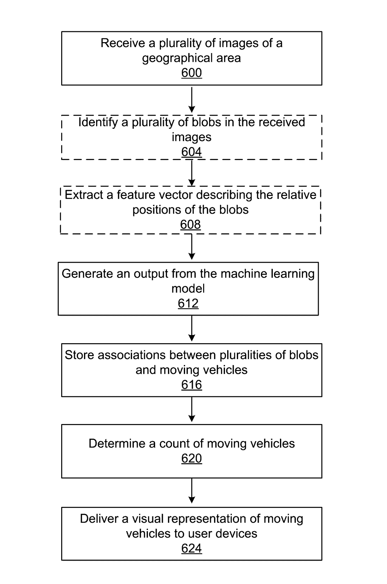
[0075]FIG. 6 illustrates an example process for the moving vehicle analysis system 101. In some embodiments, the process may have different and / or additional steps than those described in conjunction with FIG. 6. For example, optional steps are shown using dashed lines in FIG. 6. Steps of the process may be performed in different orders than the order described in conjunction with FIG. 6. Some steps may be executed in parallel. Alternatively, some of the steps may be executed in parallel and some steps executed sequentially. Alternatively, some steps may execute in a pipelined fashion such that execution of a step is started before the execution of a previous step.

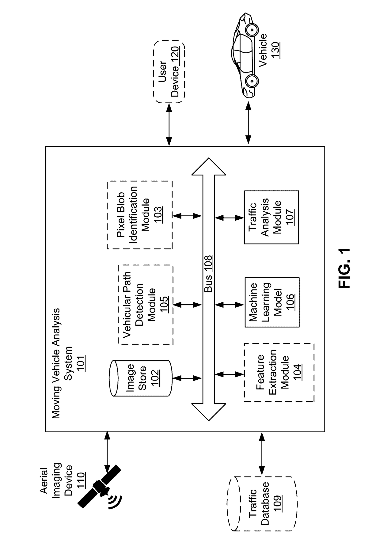
[0076]The moving vehicle analysis system 101 receives 600 images of a geographical area taken at distinct times from an aerial imaging device 110 and stores the images in an image store 102 as illustrated and described above in detail with reference to FIG. 2. An example image of a geographical area received from an aerial...

example application

of the Process

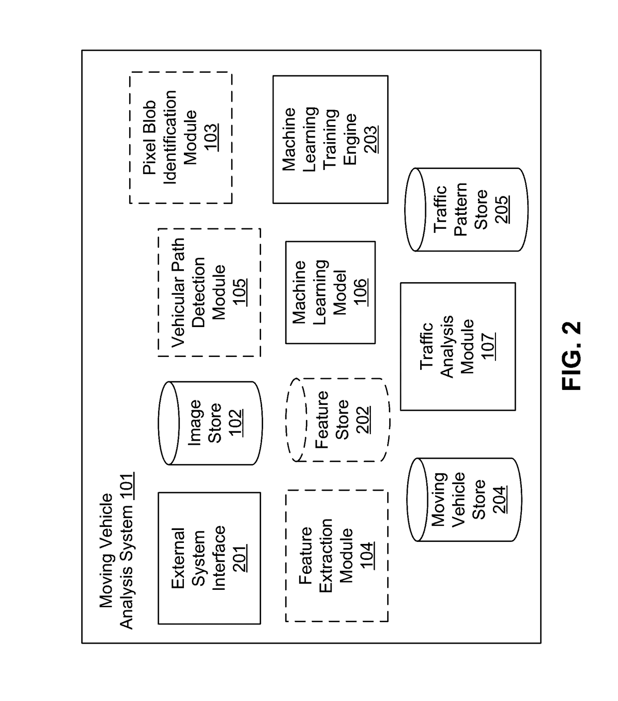
[0080]FIG. 7 illustrates an example application of the process illustrated and described above in detail with reference to FIG. 6 for the moving vehicle analysis system 101 for processing low resolution aerial imagery. The process may involve images 701, an optional pixel blob identification module 103, an image store 102, a vehicular path detection module 105, a feature vector 410, a machine learning model 106, a moving vehicle store 204, a traffic analysis module 107, a traffic database 109 and a traffic pattern store 205. Optional elements are shown using dashed lines in FIG. 7. The moving vehicle analysis system 101 receives images 701 of a geographical area via an external system interface 201, each image 701 captured at a distinct time. The images 701 may correspond to one or more spectral bands. The received images 701 shown in FIG. 7 are stored in the image store 102, as described above in detail with reference to FIG. 2.

[0081]In one embodiment, the pixel blob ...


PUM


Abstract

Disclosed is a method and system for processing images from an aerial imaging device. A moving vehicle analysis system receives images from an aerial imaging device. The system may perform edge analysis in the images to identify a pairs of edges corresponding to a road. The system may identify pixel blobs in the images including adjacent pixels matching each other based on a pixel attribute. The system uses a machine learning model for generating an output identifying moving vehicles in the images. The system determines a count of the moving vehicles captured by the images, where each moving vehicle is associated with corresponding pixel blobs.

Description

CROSS REFERENCE TO RELATED APPLICATION[0001]This application claims the benefit of U.S. Provisional Application No. 62 / 256,072, filed Nov. 16, 2015, which is incorporated by reference in its entirety.BACKGROUND[0002]Field of Art[0003]This disclosure relates generally to image processing of low resolution images and in particular to identifying moving vehicles in a geographical area using low resolution images captured by an aerial imaging device.[0004]Description of Art[0005]Several applications analyze aerial images to identify objects in the images, for example, various objects in aerial images captured by satellites. Analysis of high resolution images can be performed using relatively simple techniques. Obtaining high resolution aerial images typically requires use of large, expensive satellites and results. These satellites typically require a significant amount of resources. For example, such satellites carry sophisticated and expensive equipment such as high spatial resolution...

Claims


Application Information

Patent Timeline
IPC IPC(8): G06K9/62G06T7/60G06T7/00G06K9/00G06K9/46G06V20/13G06V10/762G06V10/774
CPCG06K9/6218G06T2207/30236G06K9/46G06K9/6256G06K9/6277G06T7/0085G06T7/606G06K9/00785G06T2207/10032G06T2207/20148G06K2009/6213G06T2207/30252G06T2207/30242G06T2207/30241G06K9/0063G06V20/13G06V20/54G06V10/454G06V10/267G06V10/462G06V10/82G06V10/762G06V10/7715G06V10/774G06F18/2132G06F18/23G06F18/214
Inventor KRAFT, ADAM WIGGENBABENKO, BORIS ALEKSANDROVICHBAXTER, MICHAEL ALANBICKERTON, STEVEN JEFFREY
Owner ORBITAL INSIGHT INC
Why Eureka
Try Eureka