Gimbaled thruster configuration for use with unmanned aerial vehicle

a technology for aerial vehicles and thrusters, which is applied in the direction of propellers, vertical landing/take-off aircraft, transportation and packaging, etc., can solve the problems of poor endurance, more difficult launch and landing, and difficult construction of uav tilt-rotor mechanisms

Active Publication Date: 2017-05-25
FLIGHTWAVE AEROSPACE SYST
View PDF10 Cites 28 Cited by
  • Summary
  • Abstract
  • Description
  • Claims
  • Application Information

AI Technical Summary

Benefits of technology

[0008]In one aspect, the disclosure describes a vectored thrust control module for an aircraft. The aircraft has an aircraft structure that includes a servo system having a motor and an output shaft that couples to the aircraft structure at a connection point. The servo system fully supports a thrust motor assembly, and the thrust motor assembly includes a motor configured to rotate a bladed component and provide thrust. Further, the thrust motor assembly is arranged with the servo system to be rigidly connected and rotatable together about a longitudinal axis thrust line with respect to the aircraft structure. The bladed component and the thrust motor assembly are configured to generate a line of thrust where a center of the line of thrust extends through the connection point of the servo system to the aircraft structure.
[0009]In another aspect, the disclosure describes a vectored thrust control module for an aircraft where the aircraft has an aircraft structure that includes servo system encased by a servo housing. The servo system includes a motor and an output shaft, wherein the output shaft is coupled to the aircraft structure at a connection point. The servo system fully supports a thrust motor assembly, and the thrust motor assembly includes a motor configured to rotate a bladed component that in turn is rotating and p...

Problems solved by technology

The multi-rotor flight mode benefits from being easy to launch and land, but it has poor endurance due in part to higher energy consumption.
The fixed-wing flight mode is beneficial due to its endurance as a result of lower energy consumption, but it is more difficult to launch and land.
UAV tilt-rotor mechanisms are difficult to build because they must be tiltable over a large range of motion, while also being durable, light, and consuming minimal power.
Some prior art attempts to overcome this required numerous small parts, making them heavy, increasing cost, increasing manufacturing complexity, increasing potential for failure, and the like.
On the other hand, some prior...

Method used


Image

  • Gimbaled thruster configuration for use with unmanned aerial vehicle
  • Gimbaled thruster configuration for use with unmanned aerial vehicle
  • Gimbaled thruster configuration for use with unmanned aerial vehicle

Examples


example 1

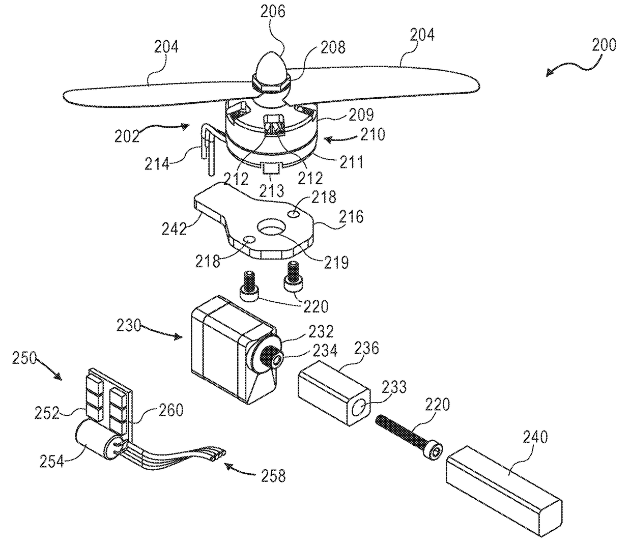
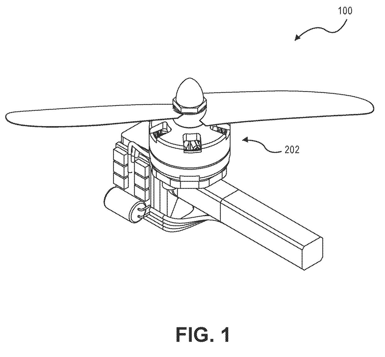
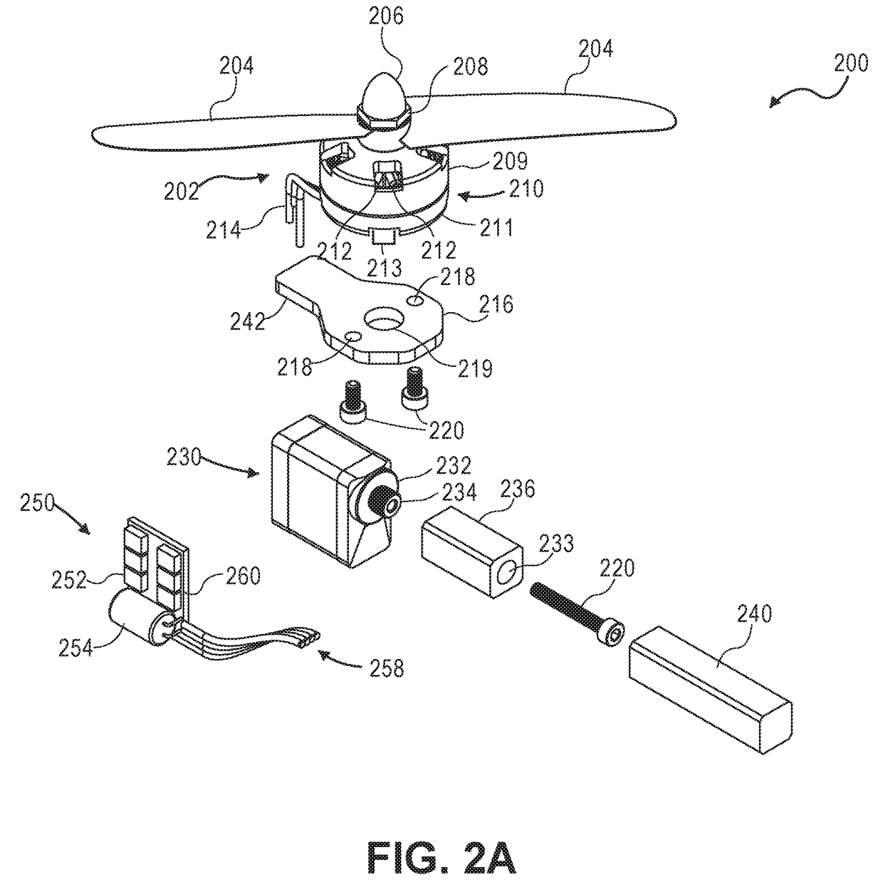
[0093]A vectored thrust control module for an aircraft having an aircraft structure comprising: a stationary servo system that includes a motor and an output shaft, wherein the stationary servo system is configured to connect at the output shaft to a servo system output arm; a bladed component configured to rotate and provide thrust; and a thrust motor assembly mounted directly to the servo system output arm of the servo system, wherein the thrust motor assembly further includes a motor that is configured to rotate the bladed component.

example 2

[0094]The vectored thrust control module according to example 1, wherein a thrust line of the thrust motor assembly aligns with a joint of the servo output shaft and frame receptacle, so as to minimize extraneous torques carried across the joint.

example 3

[0095]The vectored thrust control module of any one of examples 1 to 2, further comprising an electronic speed control unit mounted to one of the following: a frame component on the aircraft structure or the servo system, and the electronic speed control unit further powers the servo via an integrated power conditioning circuit.


PUM


Abstract

A vectored thrust control module for an aircraft that includes a servo system that couples to the aircraft structure at an output shaft connection point. A thrust motor assembly is fully supported by the servo system and rotates a bladed component to provide thrust to the aircraft. Further, the thrust motor assembly is rigidly connected with the servo system to rotate together about a longitudinal axis thrust line with respect to the aircraft structure. The bladed component and the thrust motor assembly generate a line of thrust that extends through the connection point of the servo system to the aircraft structure.

Description

CROSS-REFERENCE TO PRIOR APPLICATIONS[0001]This application claims the benefit from U.S. Provisional Application No. 62 / 258,145 filed on Nov. 20, 2015, which is hereby incorporated by reference for all purposes as if fully set forth herein.TECHNICAL FIELD[0002]The disclosure is related to a thruster configuration for use with an aerial vehicle. More particularly, the disclosure is related to a gimbaled thruster configuration for use with an unmanned aerial vehicle and a method for vectored thrust control.BACKGROUND[0003]Unmanned Aerial Vehicles (UAVs) are typically flown based on two different flight modes. The first is a multi-rotor flight mode that uses multiple lifting propellers to hover or take off and land vertically by providing generally vertical thrust. The second is a traditional fixed-wing flight mode that uses a large span aerodynamic lifting surface that uses generally horizontal thrust. The multi-rotor flight mode benefits from being easy to launch and land, but it has...

Claims


Application Information

Patent Timeline
IPC IPC(8): B64D27/26B64C11/00B64C29/00B64C39/02
CPCB64D27/26B64C39/024B64C2201/042B64C29/0033B64C2201/108B64C11/00B64U10/13B64U30/297B64U30/20B64U50/19
Inventor LUKACZYK, TRENTCOLONNO, MICHAEL
Owner FLIGHTWAVE AEROSPACE SYST
Why Eureka
Try Eureka