
Digitally Compensating for the Impact of Input Bias Current on Current Measurements

a technology of input bias current and current measurement, applied in the field of measurement systems, can solve the problems of high complexity, large input bias current of the op-amp (operational amplifier) often used as buffers for signals, and can become a significant source of errors, so as to reduce the impact of input bias current on the accuracy of current measurements and eliminate the effect of input bias current on the effect of measurement accuracy

Active Publication Date: 2017-05-25
NATIONAL INSTRUMENTS
View PDF0 Cites 11 Cited by
  • Summary
  • Abstract
  • Description
  • Claims
  • Application Information

AI Technical Summary

Benefits of technology

The patent describes a method for accurately measuring current by compensating for the impact of input bias current on measurements. This is done by using digital control loops and circuitry to digitally compensate for the impact of input bias current on current measurements. Buffers and Op-Amps with well-defined characteristics with respect to certain environmental or other type of parameters are used in the output signal path of the SMU where a high impedance node is located. By measuring the temperature and applying a correction algorithm, the impact of the input bias currents on the accuracy of the current measurements may be greatly reduced, that is, the impact of the input bias currents may be reduced below a level considered negligible in affecting the accuracy of the measurements. The technical effect of this patent is to provide a more accurate method for measuring current while compensating for the impact of input bias current on measurements.

Problems solved by technology

These SMUs were generally limited in flexibility and were high in complexity, resulting from requirements to minimize glitches during range switching.
When making low current measurements, the input bias current of the Op-Amps (Operational Amplifiers) oftentimes used as buffers for the signal can become a significant source of error.
However, present compensation methods require careful component selection which makes them susceptible to changes in process or end-of life issues associated with the selected component[s].

Method used


Image

  • Digitally Compensating for the Impact of Input Bias Current on Current Measurements
  • Digitally Compensating for the Impact of Input Bias Current on Current Measurements
  • Digitally Compensating for the Impact of Input Bias Current on Current Measurements

Examples


Embodiment Construction

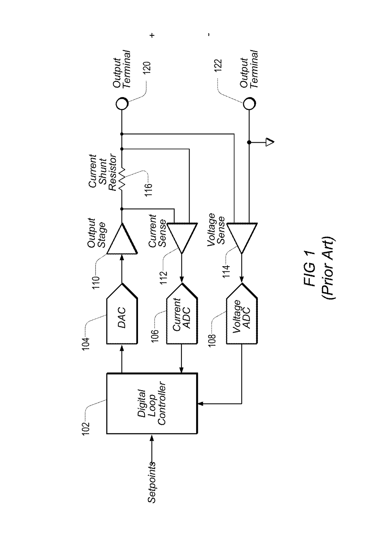
[0030]FIG. 1 shows the basic architecture of one embodiment of a prior art SMU (source-measure unit) in which the entire control loop has been configured in the digital domain. A DUT (device under test), not shown, may be coupled between output terminals 120 and 122. Setpoints and compliance limits may be provided (programmed) to Digital Loop Controller (DCL) 102, which may provide a control output through DAC (digital-to-analog converter) 104 to Output Stage 110. Feedback from Output Stage 110 may be provided to Current ADC (analog-to-digital converter) 106 and Voltage ADC 108 via respective Current Sense element 112 and Voltage Sense element 114. The current feedback may be taken from the current flowing through current shunt resistor 116, and the feedback voltage may be taken from across output terminals 120 and 122. Current ADC 106 and Voltage ADC 108 may then provide the readback current and voltage values into DCL 102.

[0031]DCL 102 may be configured to check the measured curre...


PUM


Abstract

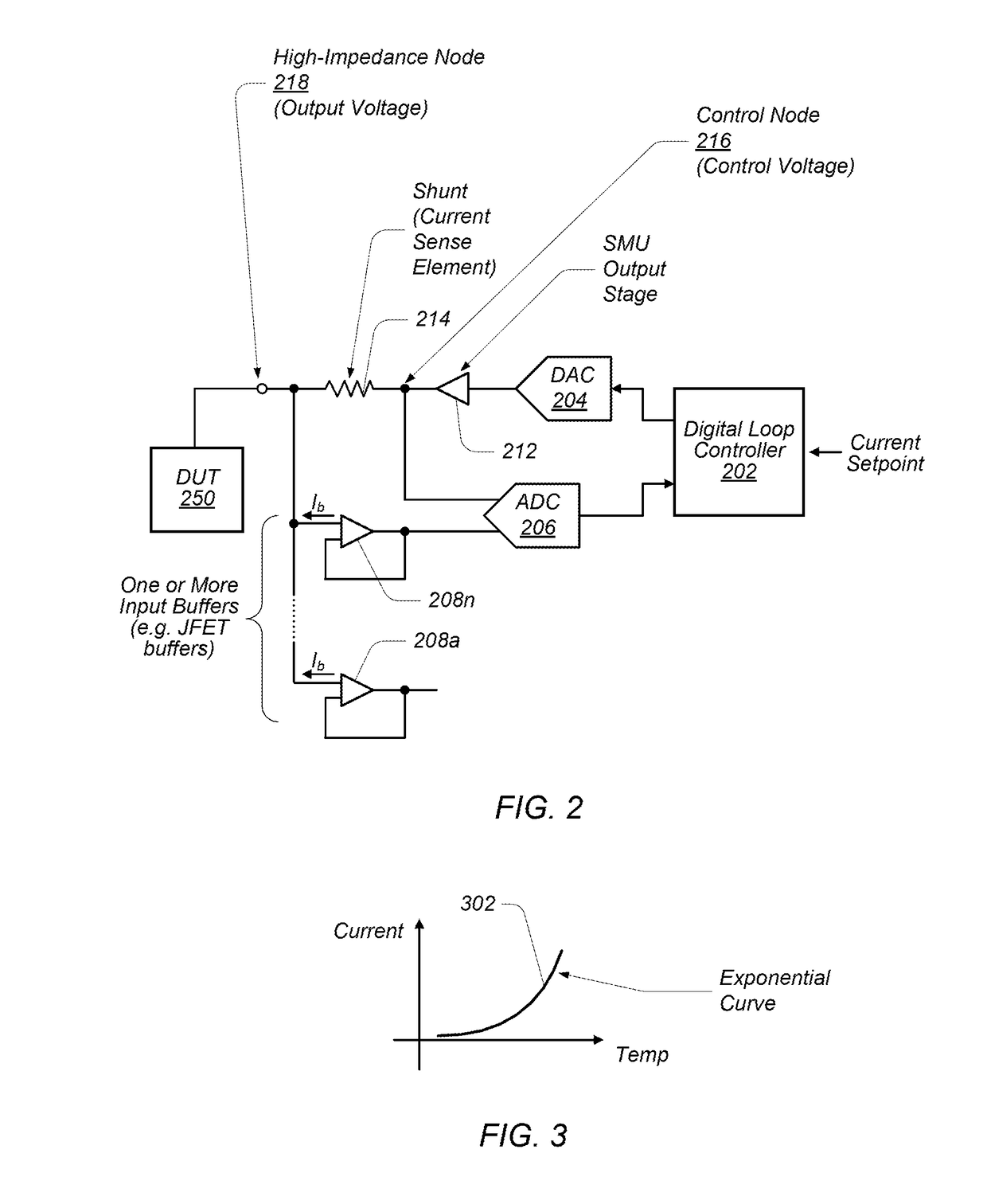
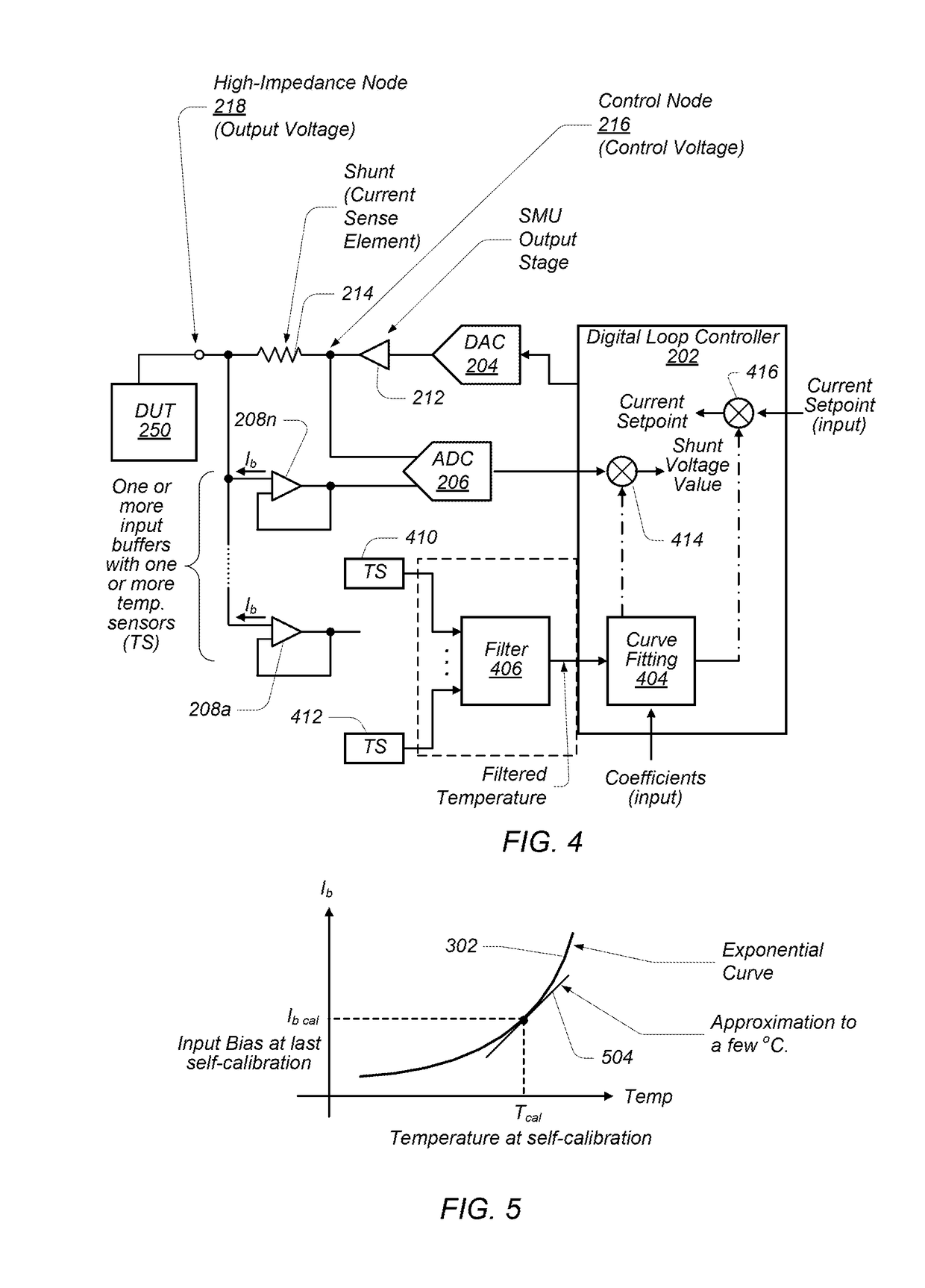
A source-measure unit (SMU) may be implemented with digital control loops and circuitry to digitally compensate for the impact of input bias current on current measurements. One or more buffers having well-defined characteristics with respect to certain parameters which may affect the current measurements may be used in the output signal path of the SMU where a shunt voltage developed across a current sense element is measured. For example, the buffers may conduct / develop respective input bias currents that change perceptibly and predictably with temperature. By measuring the temperature and adjusting a control voltage—which is used to develop the shunt voltage—according to the temperature measurements, the impact of the input bias current[s] on the current measurement[s] may be reduced to negligible levels and / or may be eliminated. The control voltage may be adjusted by adjusting a voltage feedback value representative of the measured shunt voltage, and / or by adjusting a current setpoint used for generating the control voltage.

Description

PRIORITY CLAIM[0001]This application claims benefit of priority of U.S. Provisional Patent Application Ser. No. 62 / 258,794 titled “Digitally Compensating for the Impact of Input Bias Current on Current Measurements”, filed on Nov. 23, 2015, which is hereby incorporated by reference as though fully and completely set forth herein.BACKGROUND OF THE INVENTION[0002]Field of the Invention[0003]This invention relates generally to measurement systems and, more particularly, to digitally compensating for the impact of input bias current on current measurements.[0004]Description of the Related Art[0005]Measurement systems are used to perform a variety of functions, including measurement of physical phenomena, a unit under test (UUT), or device under test (DUT), test and analysis of physical phenomena, process monitoring and control, control of mechanical or electrical machinery, data logging, laboratory research, and analytical chemistry, to name a few examples.[0006]A typical contemporary m...

Claims


Application Information

Patent Timeline
IPC IPC(8): G01R19/32G01R19/00G01R15/14
CPCG01R19/32G01R19/0092G01R15/146
Inventor LIMON-GARCIA-VIESCA, PABLO E.REGIER, CHRISTOPHER G.
Owner NATIONAL INSTRUMENTS
Learn More