Image compression method allowing a set compression quality to be obtained

a compression quality and image technology, applied in the field of image compression, can solve problems such as difficult to reconcile a complex iterative process with a limited resource implementation on a devi

Active Publication Date: 2017-05-25
THALES SA
View PDF2 Cites 2 Cited by
  • Summary
  • Abstract
  • Description
  • Claims
  • Application Information

AI Technical Summary

Benefits of technology

[0033]the size T of the semi-dead zone of the scalar quantizer being determined by minimizing the difference between

Problems solved by technology

The drawback of these solutions is that they control compression quality via a subordinate quantity, namely throughput, and most often only allow overall quality (of all the image) to be controlled and no

Method used


Image

  • Image compression method allowing a set compression quality to be obtained
  • Image compression method allowing a set compression quality to be obtained
  • Image compression method allowing a set compression quality to be obtained

Examples


Embodiment Construction

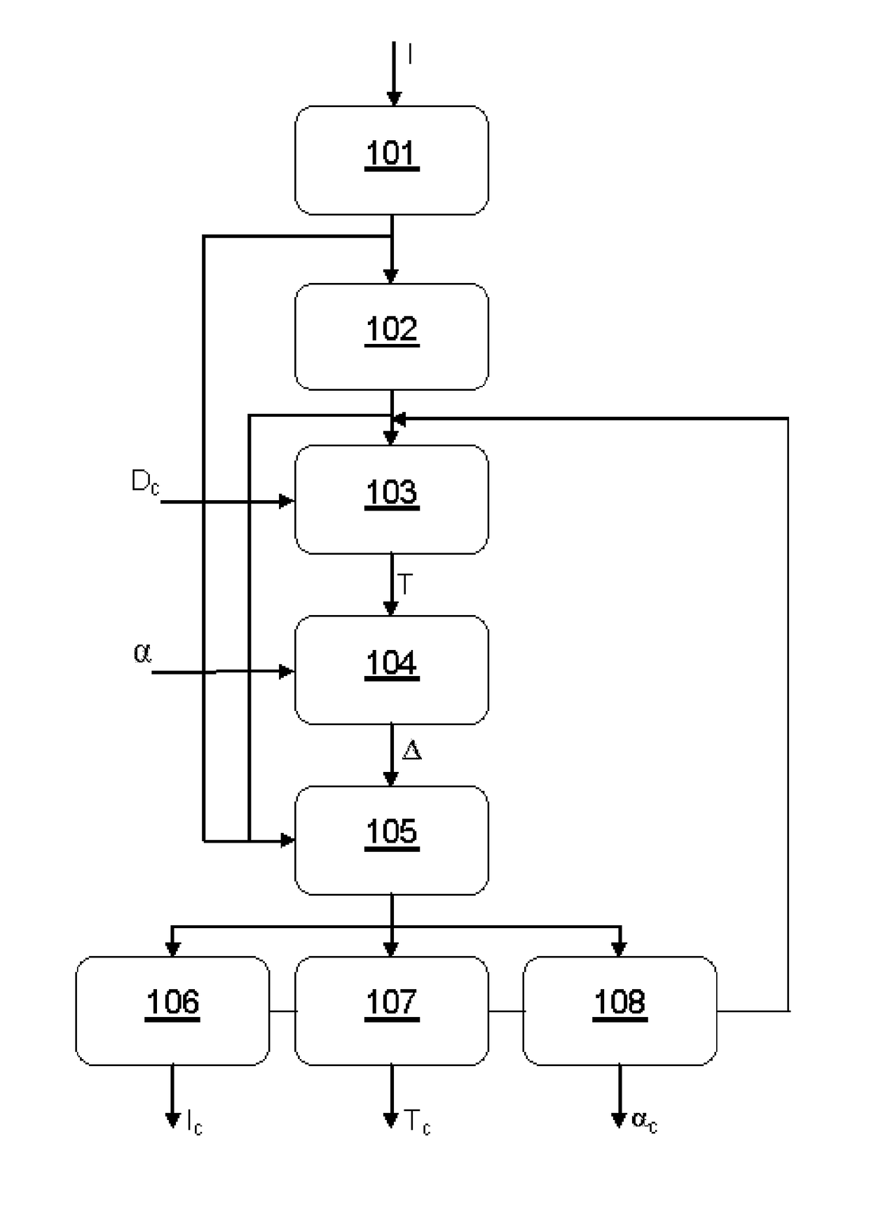
[0042]FIG. 1 illustrates, in a flowchart, the steps of the image compression method according to the invention. The method is described for compression of an image I to a coded image Ic. For an image stream comprising a succession of captured images, the method is applied sequentially and identically to each image of the stream.

[0043]This method comprises a first step 101 of decorrelating the image I by applying an orthogonal or biorthogonal mathematical transform allowing the information contained in the image to be decorrelated, for example by analysis of its frequency content. The used mathematical transform may typically be a discrete cosine transform (DCT) or a wavelet transform or any other equivalent mathematical transform. The used mathematical transform may, for example, allow a set of coefficients representative of the frequency content of the image I to be obtained. The used mathematical transform may, moreover, allow a parsimonious representation of the image to be obtai...


PUM


Abstract

An image compression method comprises the following steps applied to at least one image: decorrelating the image by applying thereto a mathematical transform to obtain a set of coefficients, decomposing the image into blocks and, for each block of the image, quantizing the coefficients using a dead-zone uniform scalar quantizer having a semi-dead zone of size T and a quantization step size Δ, and coding the quantized coefficients, the size T of the semi-dead zone of the scalar quantizer being determined by minimizing the difference between an estimated quantization distortion D(T), dependent at least on size T, and a target quantization distortion Dc.

Description

CROSS-REFERENCE TO RELATED APPLICATIONS[0001]This application claims priority to foreign French patent application No. FR 1502430, filed on Nov. 20, 2015, the disclosure of which is incorporated by reference in its entirety.FIELD OF THE INVENTION[0002]The invention relates to the field of image compression and pertains to an image compression method allowing a set compression quality to be obtained, without particular constraint on throughput.[0003]The invention is advantageously applicable to the compression of images of large size, in particular images taken by an observation satellite.BACKGROUND[0004]Known image compression methods are most often based on models in which both compression quality (or the distortion engendered by the compression operation) and the throughput obtained after compression are factors. The drawback of these solutions is that they control compression quality via a subordinate quantity, namely throughput, and most often only allow overall quality (of all ...

Claims


Application Information

Patent Timeline
IPC IPC(8): H04N19/91H04N19/63H04N19/64H04N19/176H04N19/124
CPCH04N19/91H04N19/176H04N19/63H04N19/64H04N19/124H04N19/126H04N19/12H04N19/13H04N19/147H04N19/154H04N19/94
Inventor CARLAVAN, MIKAELFALZON, FREDERIC
Owner THALES SA
Why Eureka
Try Eureka