
Imaging system for a vertebral level

a technology of x-ray imaging and vertebral level, which is applied in the field of x-ray imaging system for vertebral level, can solve the problems of few vertebral level reliably identified, and difficult or even impossible to form an x-ray image of the complete region of the spinal column of the patient. achieves the effect of easier and more reliable identification of the target vertebral level

Active Publication Date: 2017-06-01
KONINKLJIJKE PHILIPS NV
View PDF6 Cites 2 Cited by
  • Summary
  • Abstract
  • Description
  • Claims
  • Application Information

AI Technical Summary

Benefits of technology

The patent text describes an invention of an imaging system for the spine that makes it easier and more reliable to identify specific vertebral levels during interventional procedures. The system uses a series of X-ray images and a continuous panoramic image of the spine that can be stitched together to provide a safe and accurate view of the target vertebral level. This reduces the risk of mis-identifying the level and minimizes the amount of X-ray dose required while still getting sufficient coverage. The device can also provide guidance to users on which position to acquire the next frame for stitching to minimize dose.

Problems solved by technology

However, only few vertebral levels can reliably be identified from their shape or the surrounding anatomy in such assembled image.
As a result, the process is complicated and error-prone.
Using a contemporary digital X-ray examination apparatus, it is difficult or even impossible to form an X-ray image of the complete region of the spinal column of the patient to be examined in one exposure.

Method used


Image

  • Imaging system for a vertebral level
  • Imaging system for a vertebral level
  • Imaging system for a vertebral level

Examples


Embodiment Construction

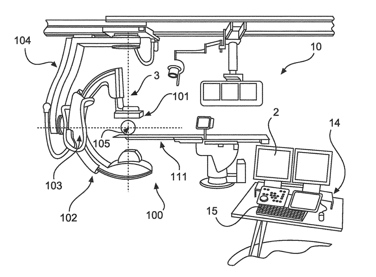
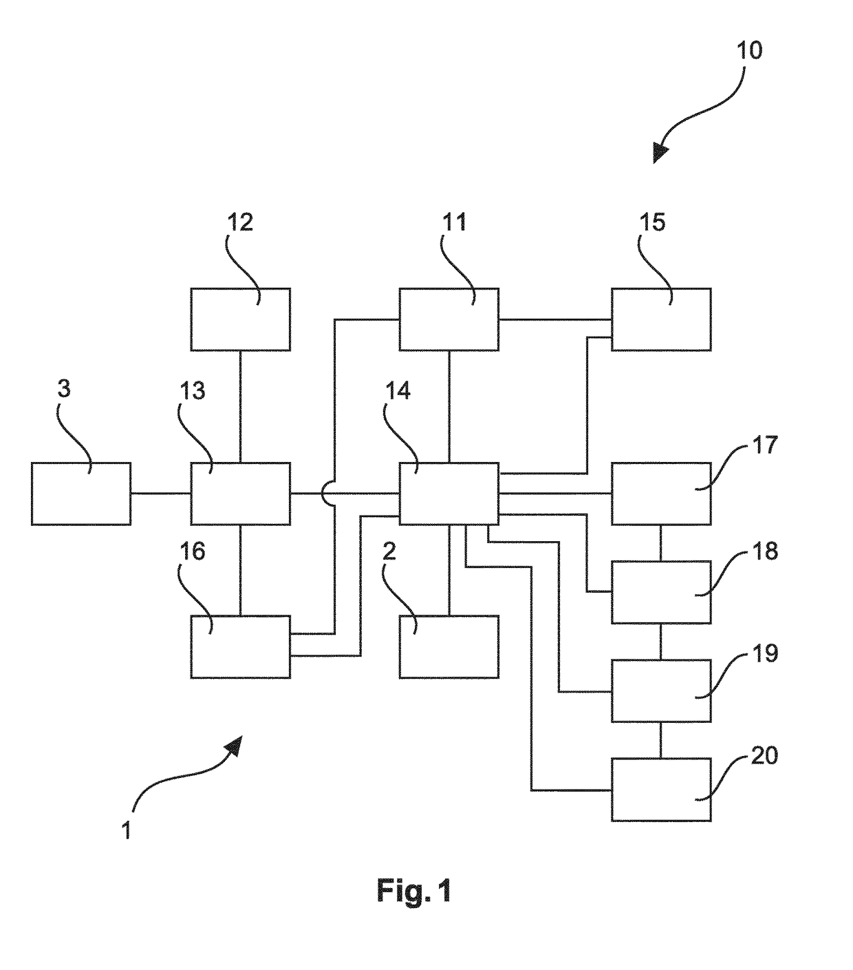
[0050]FIG. 1 shows schematically and exemplarily an embodiment of an imaging system 1 an X-ray acquisition device 3 for acquiring a series of X-ray images and a display unit 2 for displaying images. The system further comprises a patient table (not shown).

[0051]The imaging system 10 comprises a determination unit 11, a definition unit 12, an imaging unit 13 and a processing unit 14.

[0052]The determination unit 11 determines a target vertebral level. The determination may be made automatically. The determination unit may be an interface to an input device 15, so that the determination may be made manually by a user.

[0053]The definition unit 12 defines an anatomical landmark of a spine and is connected with the imaging unit 13. The imaging unit 13 provides a series of X-ray images along the spine based on the landmark. For receiving X-ray image data, the imaging unit 13 is connected with the X-ray acquisition device 3. Thus, the imaging unit 13 provides images based on X-ray image dat...


PUM


Abstract

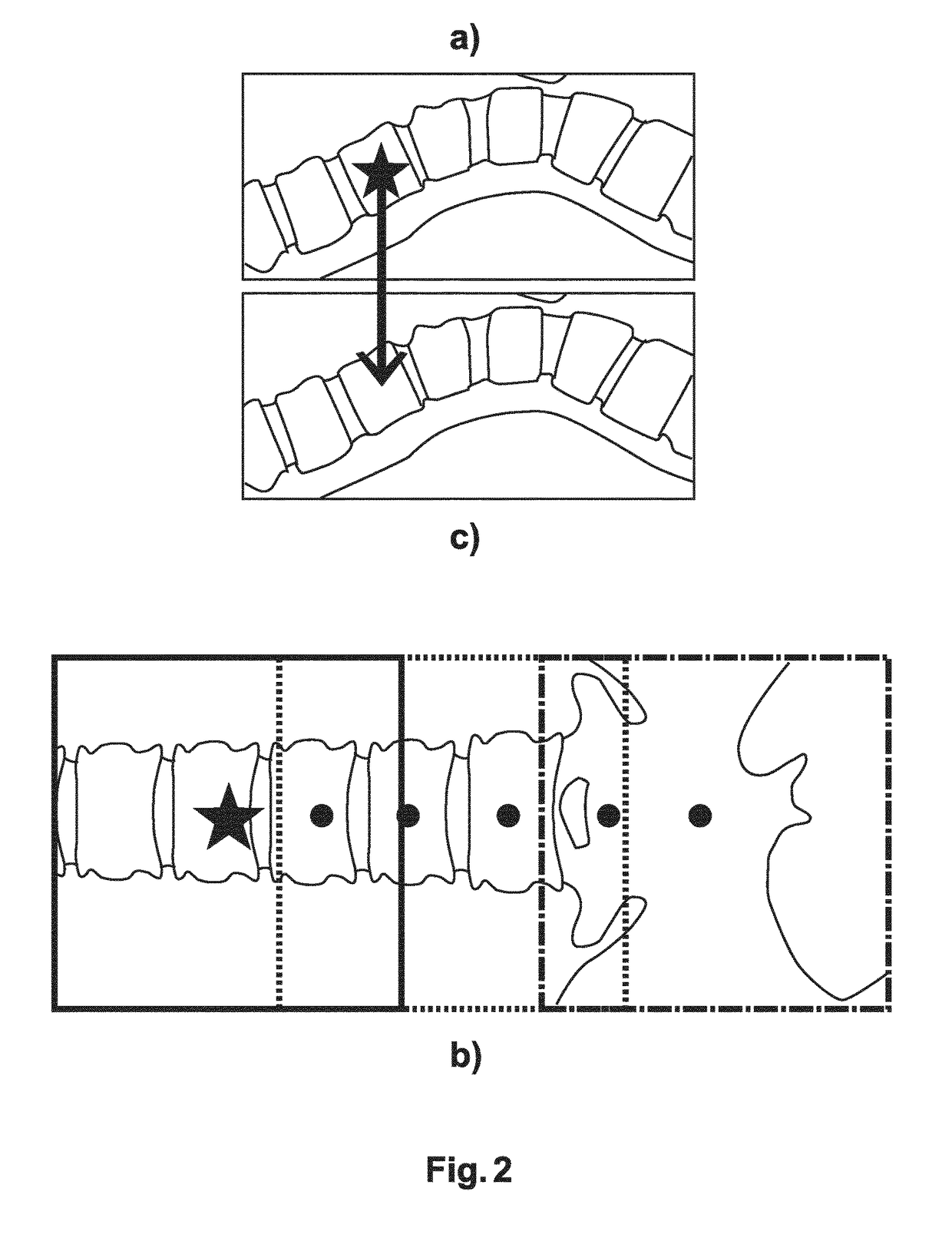
The present invention relates to an imaging system (10) for a vertebral level, an identification method for a vertebral level, a computer program element for controlling such system and a computer readable medium having stored such computer program element. The imaging system (10) comprises a determination unit (11), a definition unit (12), an imaging unit (13), and a processing unit (14). The determination unit (11) determines a target vertebral level. The definition unit (12) defines an anatomical landmark of a spine. The imaging unit (13) provides a series of X-ray images along the spine based on the landmark. The processing unit (14) identifies the target vertebral level in at least one of the X-ray images. The processing unit (14) further stitches the X-ray images to a continuous panoramic image of the spine and identifies the target vertebral level in the panoramic image.

Description

FIELD OF THE INVENTION[0001]The present invention relates to an imaging system for a vertebral level, an identification method for a vertebral level, a computer program element for controlling such system and a computer readable medium having stored such computer program element.BACKGROUND OF THE INVENTION[0002]In minimally invasive spine interventions, it is very important to localize the correct vertebral level for treatment. The interventions are usually performed under X-ray guidance, with the X-ray system offering only a limited field-of-view. However, only few vertebral levels can reliably be identified from their shape or the surrounding anatomy in such assembled image. Therefore, the vertebral level has to be identified by palpitation and counting of landmarks or from visually assessing projection images from the limited X-ray field-of-view. As a result, the process is complicated and error-prone.[0003]In digital X-ray imaging, a composition of an image from sub-images is ge...

Claims


Application Information

Patent Timeline
IPC IPC(8): A61B6/00G06T11/60G06T7/73A61B5/00
CPCA61B6/505A61B5/4566A61B6/5276A61B6/4441A61B6/4464G06T2207/30012A61B6/547G06T11/60G06T7/73G06T2207/10116A61B6/5241A61B6/00
Inventor HANSIS, EBERHARD SEBASTIANSCHAEFER, DIRKGRASS, MICHAEL
Owner KONINKLJIJKE PHILIPS NV
Learn More