System for sending signals between modules

a technology of sending signals and modules, applied in the field of sending signals between modules, can solve the problems of not being able to control the output of pulse signals, not enabling the handling of failures in the harness, etc., and achieve the effect of preventing the effective transmission of incorrect signals and easy and reliable identification

Active Publication Date: 2012-12-25
YAMATAKE HONEYWELL CO LTD
View PDF9 Cites 2 Cited by
  • Summary
  • Abstract
  • Description
  • Claims
  • Application Information

AI Technical Summary

Benefits of technology

[0018]Given the structure set forth above, the sending-side module generates a single time series pulse signal by a combining pulse signals generated through time division by the plurality of signal generating units and this time series pulse signal is transmitted to the receiving-side module through a relay, enabling the easy and reliable identification of an interruption in the signal that indicates the presence of data, from a skip in the pulse signal on the receiving-side module. Furthermore, on the sending-side module, the monitoring of the signals (pulse signals) that appear, respectively, at the normally-open contact point and the normally-closed contact point of the relay when the relay is driven and when the relay is not driven enables the easy evaluation as, to whether or not a failure has occurred in the relay, or the like (that is, a self-diagnostic function). Consequently, stopping the pulse signal generating operation itself when a failure has occurred can prevent effectively the transmission of an incorrect signal to the receiving-side module.

Problems solved by technology

However, the technique disclosed in this JP '502 does no more than enable the handling of failures in the harness.
However, when a relay is used in parallel, there are the new problems of not being able to control the output of the pulse signal due to a failure of a relay (that is, when a relay contact point fuses).

Method used


Image

  • System for sending signals between modules
  • System for sending signals between modules
  • System for sending signals between modules

Examples


Embodiment Construction

[0023]The system for transmitting signals between modules as set forth in one example of embodiment according to the present invention will be explained below in reference to the figures.

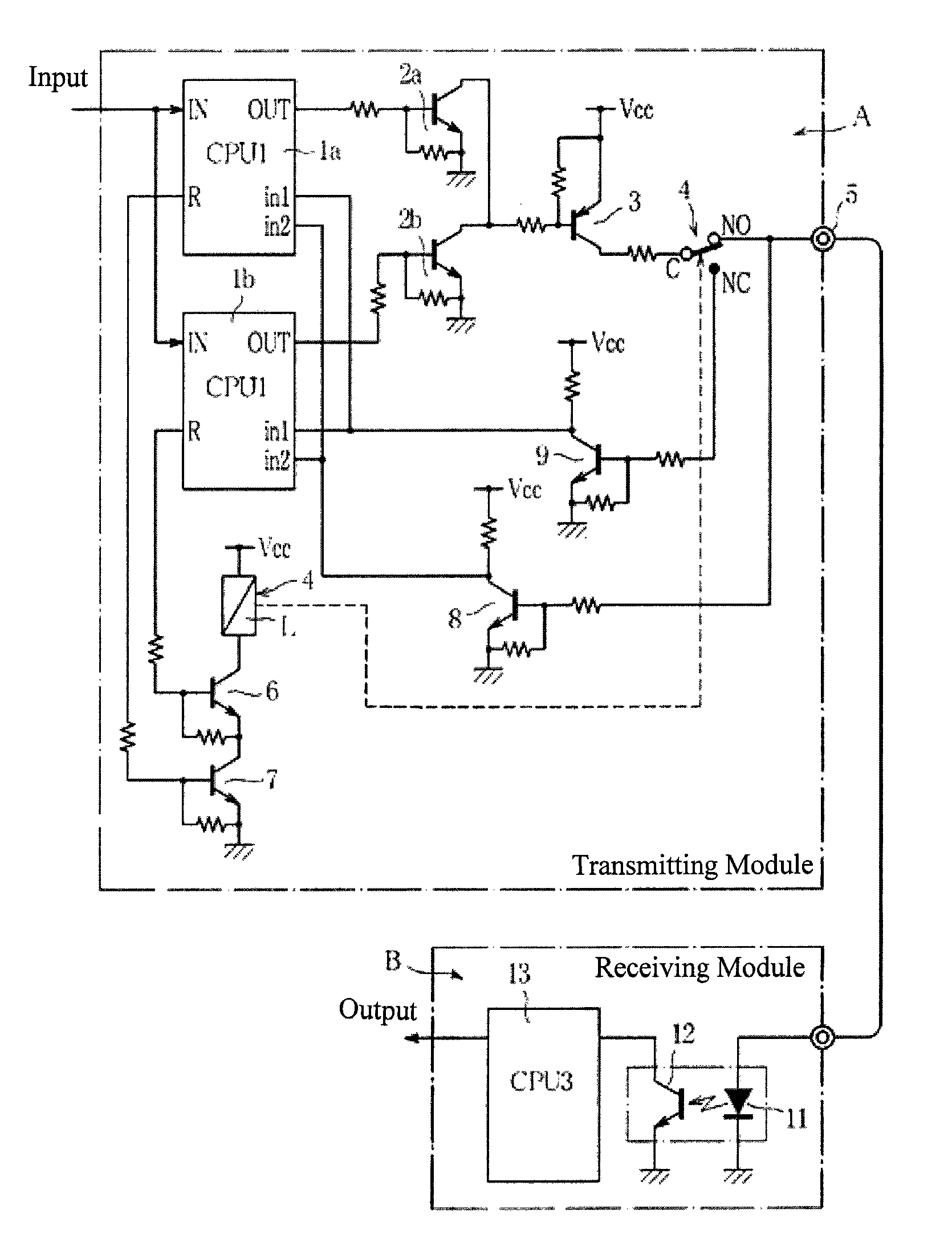
[0024]FIG. 1 is a diagram illustrating an example of a structure for a sending-side module and a receiving-side module for achieving the system for transmitting signals between modules. In FIG. 1, A is a transmitting module (monitoring module) for monitoring interlocks in, for example, a combustion furnace and for outputting a “burner operation permitted” signal, and B is a receiving module (combustion controlling module) for receiving the “burner operation permitted” signal and controlling the combustion of the burner.

[0025]The transmitting module A is provided with two control devices (CPUs) 1a and 1b, in parallel, that input interlock signals and generate pulse signals of specific periods, where information (a pulse signal) indicating the existence of an interlock signal is produced in multiplex ...


PUM


Abstract

A system for transmission of signals between modules wherein, for example, it is possible to transmit reliably, between modules, information relating to, for example, the actuation of safety devices. A transmission module for transmitting a pulse signal of a specific period, which indicates the existence of information, generates, in time division, pulse signals by a plurality of signal generating units that are provided in parallel, and then combines these pulse signals into a single time series pulse signal. Then an attempt is made to output this pulse signal towards a receiving-side module through a relay for controlling the output, and the signals appearing at a normally-open terminal and at a normally-closed terminal of the relay are monitored to determine whether or not there is a failure, where the generation of the pulse signal is stopped when a failure is detected.

Description

CROSS REFERENCE TO RELATED APPLICATIONS[0001]The present application claims priority under 35 U.S.C. §119 to Japanese Patent Application No. 2009-128921, filed May 28, 2009, which is incorporated herein by reference.FIELD OF TECHNOLOGY[0002]The present invention relates to a system for sending signals between modules, capable of sending, for example, information regarding the actuation of a safety device, reliably between modules.BACKGROUND OF THE INVENTION[0003]An operating control system for a combustion furnace is provided with a monitoring module for monitoring interlocks pertaining to safety operations of the combustion furnace, and a combustion control module for controlling the operation of the burner in the combustion furnace. Furthermore, in the monitoring module, interlocks pertaining to safety operations of the combustion furnace are monitored, where only when the interlocks are in the normal state is a “burner operation permitted” signal sent to the combustion control mo...

Claims


Application Information

Patent Timeline
Patent Type & Authority Patents(United States)
IPC IPC(8): H03M13/00
CPCG05B9/03G05B19/0425G05B2219/24184G01R31/3278H04L1/22
Inventor YAMADA, AKIRAKUMAZAWA, YUUICHIMORIKAWA, KATSUMI
Owner YAMATAKE HONEYWELL CO LTD
Why Eureka
Try Eureka