Slide cushion device of press machine

a technology of cushion device and press machine, which is applied in the direction of manufacturing tools, metal-working apparatus, shaping tools, etc., to achieve the effect of cushion pressure, saving power cost, and increasing degree of freedom

Active Publication Date: 2017-06-01
AIDA ENG LTD
View PDF5 Cites 2 Cited by
  • Summary
  • Abstract
  • Description
  • Claims
  • Application Information

AI Technical Summary

Benefits of technology

[0031]In a slide cushion device of a press machine according to yet another aspect of the present invention, the slide cushion hydraulic device is filled with pressurized operation fluid, and no hydraulic pump for pressurizing and supplying the operation fluid is provided between the cushion pressure generating line and the system pressure acting line. When the slide cushion pressure acts, the logic valve operates as a main relief valve to enable slide cushion pressure corresponding to pilot pressure generated by the pilot relief valve to be generated, and descending operation of the piston member, including operation of pushing out a product, can be performed by using operation fluid under the system pressure accumulated in the accumulator, whereby a hydraulic pump is unnecessary. As described above, since a hydraulic pump is unnecessary, power cost can be saved.
[0032]According to the present invention, when an area in a recessed portion of an upper die for a material to be press-formed is pressed from above by the pressing member, the number and placement of cushion pins for the pressing member can be appropriately adjusted for each die while a degree of freedom is increased. In addition, cushion pressure is generated with a quick response, substantially constant cushion pressure can be controlled, the cushion pressure can be reduced after forming is finished, and an inexpensive device can be achieved.

Problems solved by technology

In addition, since the rod-less cylinder is a gas enclosed type, there is a problem in that increase in pressure with a cushion stroke during press forming, and residual cushion pressure after forming, have no small adverse effect on forming.

Method used


Image

  • Slide cushion device of press machine
  • Slide cushion device of press machine
  • Slide cushion device of press machine

Examples


Embodiment Construction

[0043]With reference to accompanying drawings, preferable embodiments of a slide cushion device of a press machine according to the present invention will be described below in detail.

[Structure of Whole of Press Machine]

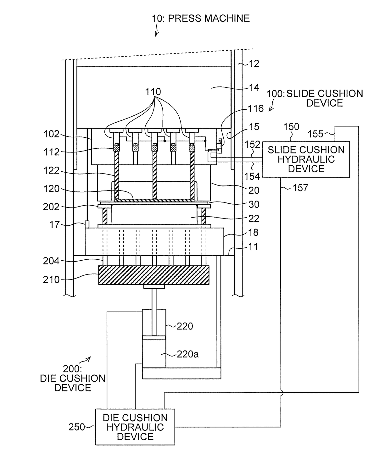
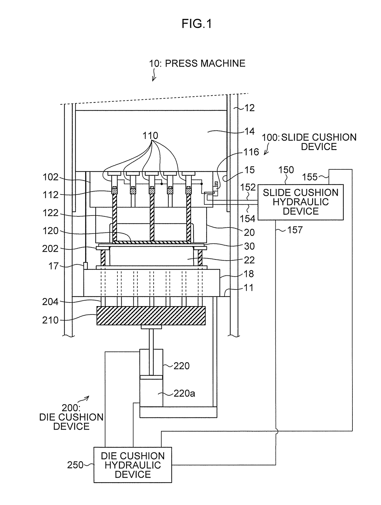
[0044]FIG. 1 is a schematic structural view of the whole of a press machine including a slide cushion device according to the present invention.

[0045]In FIG. 1, a press machine 10 includes a frame including a bed 11, a column 12, and a crown (not illustrated), and a slide 14 that is movably guided in a vertical direction by a guide section 15 provided in the column 12. The slide 14 is moved in the vertical direction in FIG. 1 by a servo motor (not illustrated), or a crank mechanism including a crankshaft to which rotational driving force is transmitted by a flywheel (not illustrated).

[0046]It is preferable that a slide position detector 17 for detecting a position of the slide 14 is provided on a bed 11 side of the press machine 10, or that the crankshaft of the cra...


PUM

PropertyMeasurementUnit
pressureaaaaaaaaaa
degree of freedomaaaaaaaaaa
hydraulic pressureaaaaaaaaaa

Abstract

A slide cushion device includes: a hydraulic cylinder group integrally formed in a board provided immediately below a slide; a pressing member that is disposed in a recessed portion of an upper die that vertically moves together with the slide, in a vertically movable manner; a plurality of slide cushion pins that is provided in the pressing member and penetrates the upper die to be brought into contact with a piston member of the hydraulic cylinder group, wherein a number of the cushion pins is less than a number of hydraulic cylinders disposed in a plane of projection of the recessed portion; and a slide cushion hydraulic device that controls hydraulic pressure to be supplied to a compression chamber of the hydraulic cylinder with which a slide cushion pin is to be brought into contact.

Description

BACKGROUND OF THE INVENTION[0001]Field of the Invention[0002]The present invention relates to a slide cushion device of a press machine, and more particularly to a slide cushion device of a press machine, the slide cushion device pressing from above an area in a recessed portion of an upper die for a material to be press-formed.[0003]Description of the Related Art[0004]In recent years, forming of a high-tensile steel plate by using a press machine has become common, and a function of a slide (upper side) cushion that presses from above an area in a recessed portion of an upper die for the high-tensile steel plate during press forming is important to improve formability of the high-tensile steel plate.[0005]Conventionally, there is provided a device for a press die that is to be used by being attached to a press machine, and that includes a work holding pad for holding a work, the work holding pad being movable up and down (refer to Japanese Patent Application Laid-Open No. 2006-0619...

Claims


Application Information

Patent Timeline
Patent Type & Authority Applications(United States)
IPC IPC(8): B21D24/02
CPCB21D24/02B21D37/12B21D24/14B21D24/08
Inventor KOHNO, YASUYUKI
Owner AIDA ENG LTD
Why Eureka
Try Eureka