Welding torch maintenance center

a welding torch and maintenance center technology, applied in the field of welding torch maintenance, can solve the problems of affecting the gas flow of mig welding, restricting the gas flow, and affecting the service life of the welding torch

Active Publication Date: 2017-06-01
NASARC TECH
View PDF4 Cites 3 Cited by
  • Summary
  • Abstract
  • Description
  • Claims
  • Application Information

AI Technical Summary

Benefits of technology

[0011]The welding torch maintenance apparatus and the welding tip changing apparatus may include an actuating means for providing a degree of movement freedom for the second gripping means in a direction parallel to the rotational axis.
[0014]According to a yet another aspect of the invention, a method is provided for replacing a welding tip which include fastening a diffuser of a welding torch; holding a welding tip of the welding torch and rotating the welding tip about a rotational axis to remove the welding tip; providing a new welding tip; and attaching the new welding tip to the welding torch, wherein a degree of movement freedom is provided along the rotational axis.

Problems solved by technology

Gas flow in MIG welding can be adversely affected by weld spatter of the melted welding wire which can adhere to nozzle, welding tip or other components of a welding torch disposed about the welding tip.
Weld spatter is a hard material and is known to build up to a considerable degree if not removed periodically, and consequently restrict the gas flow between the nozzle and the welding tip.
Weld spatter that accumulates on the nozzle or the welding tip can also build up to a point at which weld wire feed is impeded and the arc welding process is damaged.
This decreases the reliability and performance of the weld.
The accumulation of weld splatter also decreases the physical distance between the charged welding tip and the electrically insulated nozzle.
This results in a diminished amount of electrical energy being delivered to the weld site.
Therefore, if the buildup continues to excess, a complete breakdown of the welding process may result.
While anti-spatter compounds are available for spray application to the gas nozzle or the welding tip, they serve only to delay the deposition of spatter, not to prevent it.
Cleaning torch components manually is generally inefficient, considering the high cost of operating an assembly line with the robotic welding machine.

Method used


Image

  • Welding torch maintenance center
  • Welding torch maintenance center
  • Welding torch maintenance center

Examples


Embodiment Construction

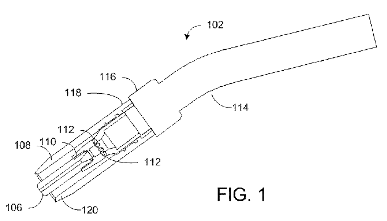
[0050]Referring to the drawings, FIG. 1 shows a welding torch 102 used in connection with the welding torch maintenance center according to an embodiment of the invention. The welding torch 102 includes an open cylindrical nozzle 108 and a central, electrically charged welding tip 106 for extending weld wire (not shown). The welding tip 106 is attached to a gas diffuser 110, the gas diffuser 110 being connected to a gas source (not shown) and including holes 112 for distributing gas into the nozzle 108 to control the welding environment at the weld. At a proximal end 118 of the nozzle 108, the nozzle 108 may be mounted to a welding arm or collar 116 of the welding torch 102. The connection between the nozzle 108 and the welding arm or collar 116 of the welding torch 102 may be of a threaded or a slipped-on type. The welding tip 106 may be connected to the diffuser 110 via a thread, and is in concentric relationship with the nozzle 108. The welding tip 106 may protrude a distal end 1...


PUM

PropertyMeasurementUnit
degree of movement freedomaaaaaaaaaa
vertical movementaaaaaaaaaa
movementaaaaaaaaaa

Abstract

A welding torch maintenance apparatus and a welding tip changer are described. The welding torch maintenance apparatus and the welding tip changing apparatus each comprise a first gripping means for fastening the welding torch / diffuser so that the nozzle / welding tip is aligned with the rotational axis, a second gripping means for holding the nozzle / welding tip, the second gripping means rotates about the rotational axis to remove the nozzle / welding tip, and moves along the rotational axis. A drive means is provided for rotating the second gripping means, and a lift system is provided for moving the second gripping along the rotational axis. The welding torch maintenance apparatus further includes a cleaning means which enters the nozzle at the distal end and cleans an interior of the nozzle.

Description

FIELD OF THE INVENTION[0001]The present invention relates to maintenance of a welding torch, and more specifically, to a welding torch maintenance center.BACKGROUND OF THE INVENTION[0002]A well-known welding technique is arc welding whereby the welding electrodes are deliberately consumed during the welding process, and come to form an integral component of the welded product.[0003]Metal-inert-gas (“MIG”) arc welding is an arc welding technique in which a relatively fine wire electrode is fed continuously from a large spool with a variable speed drive whose speed is controlled to optimize arc length and burnoff rate. During the welding process, the electrical arc that extends between the electrode and the metal surfaces that are being welded, is shielded within a gas flow. Argon or other gases with suitable characteristics such as carbon dioxide may be used.[0004]Gas flow in MIG welding can be adversely affected by weld spatter of the melted welding wire which can adhere to nozzle, ...

Claims


Application Information

Patent Timeline
Patent Type & Authority Applications(United States)
IPC IPC(8): B23K9/32B23K9/26
CPCB23K9/26B23K9/328
Inventor KTEILY, NASEEM E.
Owner NASARC TECH
Why Eureka
Try Eureka