Internal combustion engine

a combustion engine and internal combustion technology, applied in the direction of machines/engines, mechanical equipment, cylinders, etc., can solve the problem of not being able to efficiently cool the exhaust port, and achieve the effect of suppressing the thermal deformation of the exhaust port and reducing the thermal influen

Inactive Publication Date: 2017-06-01
NISSAN MOTOR CO LTD
View PDF18 Cites 32 Cited by
  • Summary
  • Abstract
  • Description
  • Claims
  • Application Information

AI Technical Summary

Benefits of technology

[0009]In the present invention, by providing the partition wall, it is possible to decrease the thermal influence which the coolant around the exhaust port receives from the combustion chamber, relative to the coolant around the intake port. Accordingly, it is possible to be easy to cool the exhaust port, and thereby to suppress the thermal deformation of the exhaust port.

Problems solved by technology

With this, it may not be possible to efficiently cool the exhaust port.

Method used


Image

  • Internal combustion engine
  • Internal combustion engine
  • Internal combustion engine

Examples


Embodiment Construction

[0014]Hereinafter, an in-line three-cylinder internal combustion engine of SOHC type according to one embodiment of the present invention is explained in detail based on the drawings

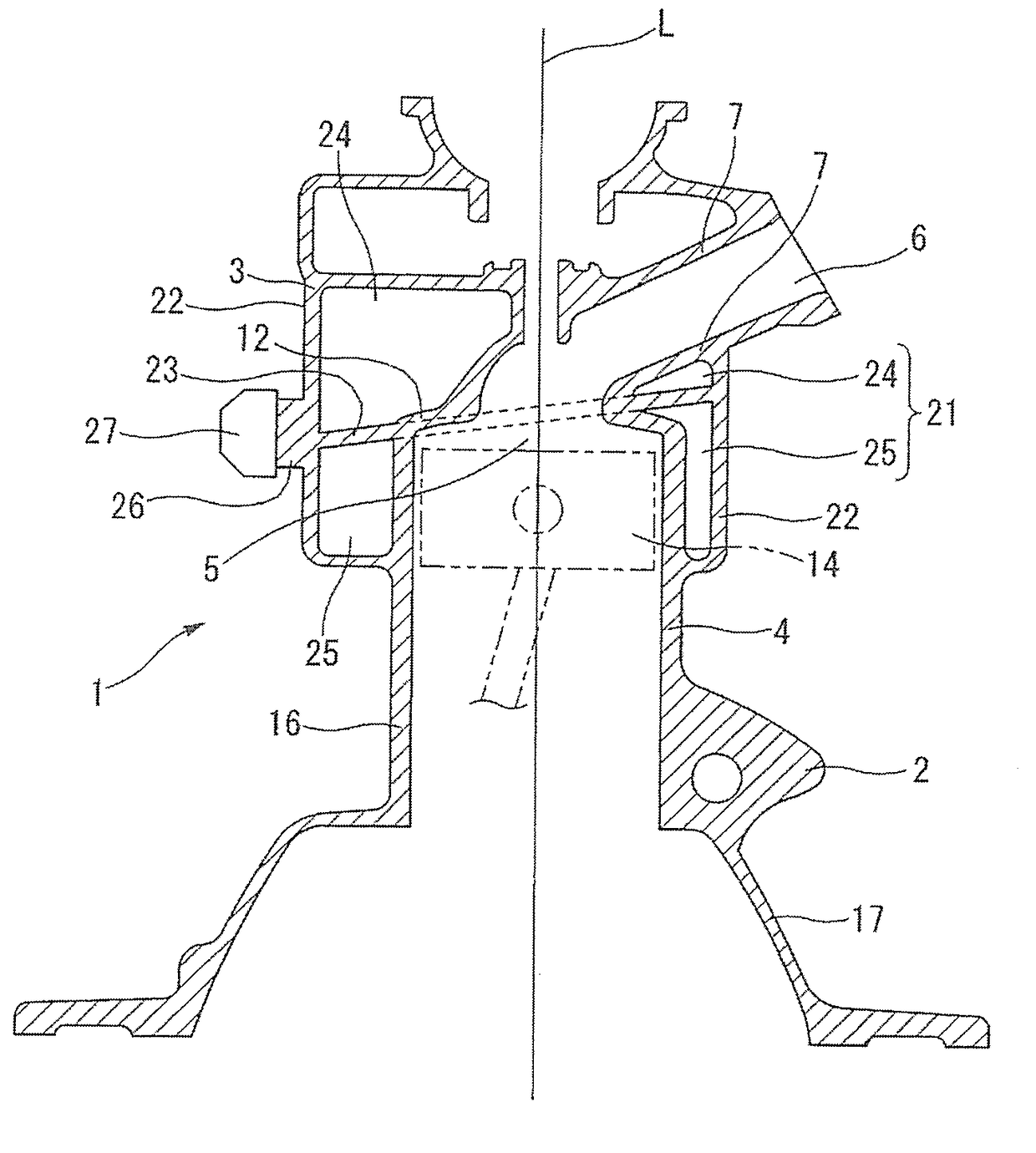
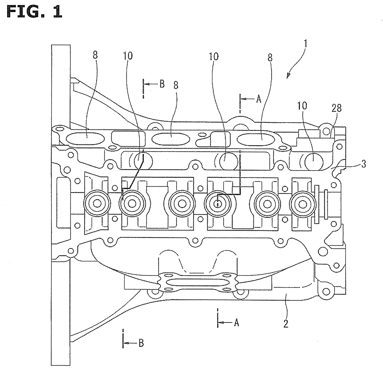
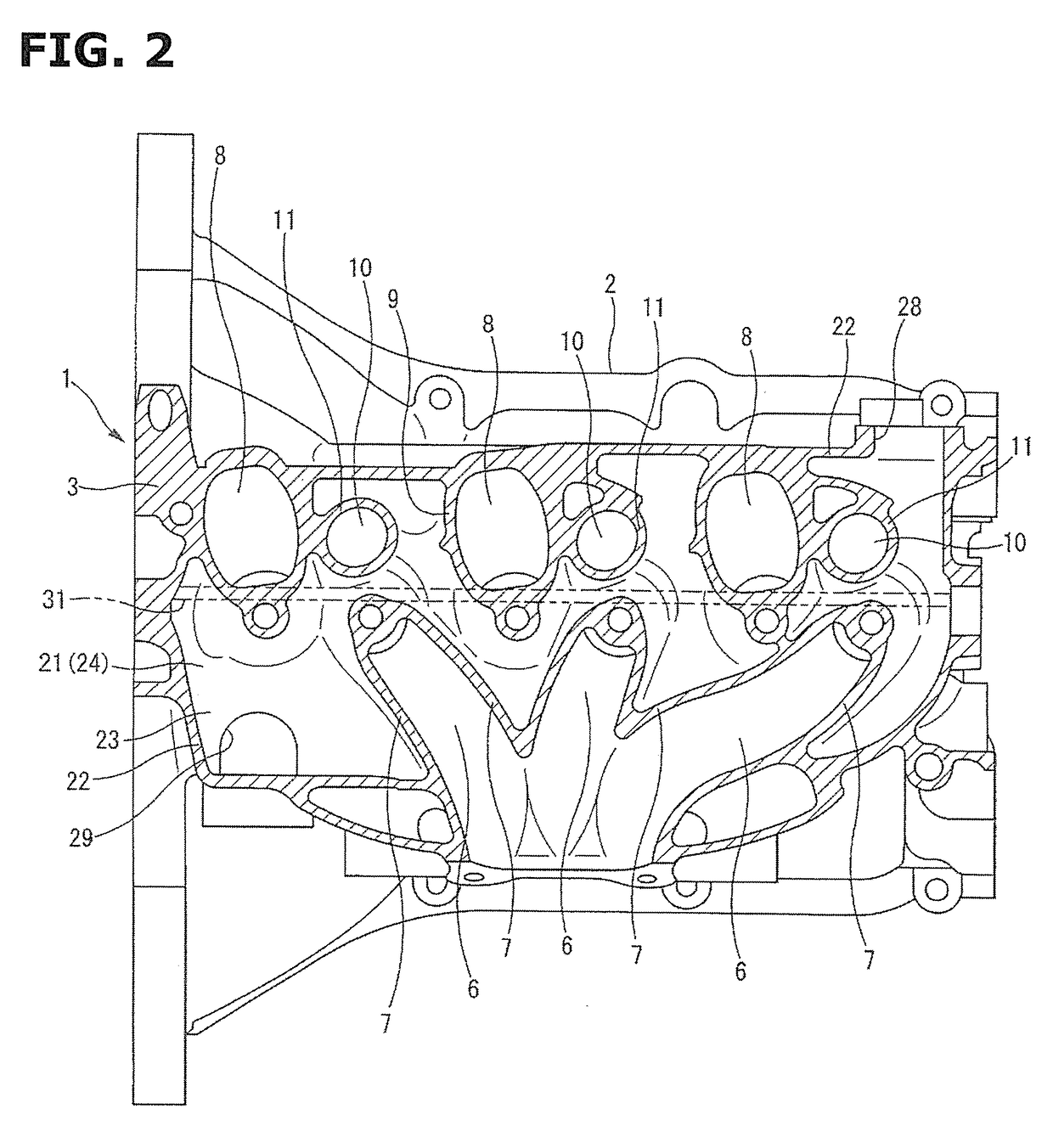
[0015]FIG. 1 to FIG. 4 show explanation views showing an internal combustion engine 1 to which the present invention is applied. FIG. 1 is a plan view. FIG. 2 is a sectional view showing main parts. FIG. 3 is a sectional view taken along a section line A-A of FIG. 1. FIG. 4 is a sectional view taken along a section line B-B of FIG. 1.

[0016]The internal combustion engine 1 according to embodiment is made from metal material such as aluminum alloy. Portions of the internal combustion engine 1 are integrally casted. The internal combustion engine 1 includes a cylinder block 2 in which three cylinders 4 are disposed in series with one another, and a cylinder head 3 covering upper ends of the cylinders 4 so as to form a combustion chamber 5. The cylinder block 3 and the cylinder head 4 are integrally formed w...


PUM


Abstract

An internal combustion engine includes: a cylinder block in which a cylinder is formed; a cylinder head including an intake port and an exhaust port, the cylinder head being integrally formed with the cylinder block; a water jacket covering circumferences of the cylinder, the intake port, and the exhaust port; and a partition wall dividing the water jacket into a cylinder block side and a cylinder head side, the partition wall being inclined so that an exhaust port side is positioned nearer to a cylinder head side than an intake port side.

Description

TECHNICAL FIELD[0001]This invention relates to an internal combustion engine in which a cylinder head and a cylinder block are integrally casted.BACKGROUND ART[0002]In many internal combustion engines which are actually used for vehicles, a cylinder block and a cylinder head are separately (independently) casted, the cylinder block and the cylinder head are tightened by a plurality of cylinder head bolts.[0003]Contrary to this, a patent document 1 discloses an internal combustion engine in which a cylinder head and a cylinder block are integrally casted. In the patent document 1, a water jacket is divided by a partition wall into a head side water jacket around a combustion chamber, and a cylinder side water jacket around the cylinder, so as to adequately adjust temperature distributions of the cylinder head side and the cylinder block side.[0004]The head side water jacket is arranged to forcibly circulate the coolant from one end side of a cylinder row direction toward the other en...

Claims


Application Information

Patent Timeline
Patent Type & Authority Applications(United States)
IPC IPC(8): F01P3/02F02F1/36F01P7/14F02F1/24F02B77/08F02F1/10F02F1/42
CPCF01P3/02F02F1/10F02F1/36F02F1/4285F02F1/242F01P2037/02F01P7/14F01P2003/021F01P2003/024F01P2003/028F02B77/085F02F1/14F02D35/00F02F1/002
Inventor KUBO, YUITO, TAKAO
Owner NISSAN MOTOR CO LTD
Why Eureka
Try Eureka