
Eureka
For R&D, Eureka makes reading and utilizing patents & technical documents easy.
Eureka AIR
Designed for self-driven R&D workflows. Generate viable solutions, solve complex R&D challenges, empower your innovation with AI.

Eureka Materials
Designed for material experts only. Revolutionize your material R&D, from search, analyze, to developing new materials.

TechResearch
Generate reliable direction feasibility study reports for your R&D in just a few steps.

TechSeek
Discover and master advanced knowledge NOW. Basics, ideas, possibilities, all at once.

TechMind
As an expert in R&D Theories, TechMind can generates customized viable solutions instantly.

TechRisk
Analyze your overall solution with one click, know your potential R&D risks in advance.

TechMonitor
Get weekly tech updates, stay abreast of the latest tech innovations and key insights.
Engine control apparatus
- Summary
- Abstract
- Description
- Claims
- Application Information
AI Technical Summary
Benefits of technology
Problems solved by technology
Method used
Image

Examples
first embodiment
[0033]A first embodiment of this invention will be described below with reference to the drawings.
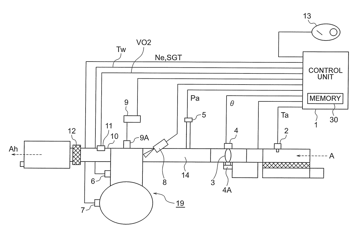
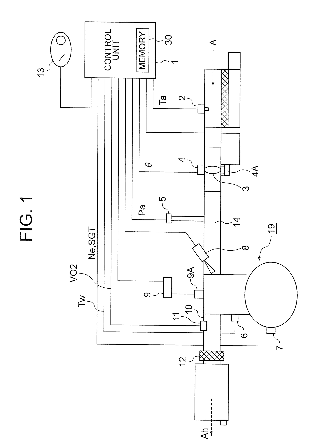
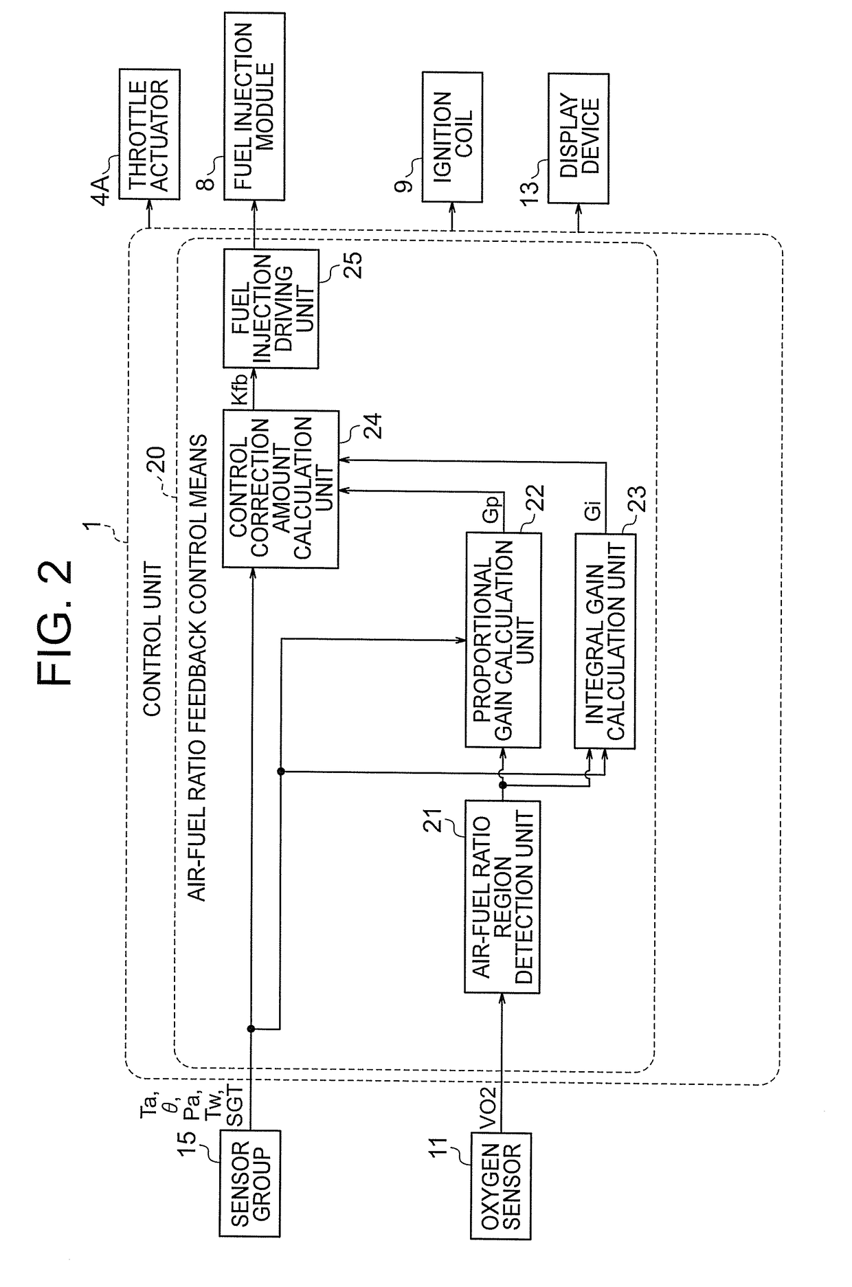
[0034]FIG. 1 is a view showing a configuration of an engine control apparatus according to the first embodiment of this invention when attached to an engine of a vehicle. FIG. 2 is a block diagram showing a functional configuration of a control unit 1 shown in FIG. 1. FIG. 3 is an illustrative view showing a relationship between an output characteristic of an oxygen sensor and air-fuel ratio regions of the engine, according to the first embodiment.
[0035]In FIG. 1, the control unit 1 constitutes a main portion of the engine control apparatus. The control unit 1 is constituted by a microcomputer having a CPU (not shown) and a memory 30. The control unit 1 stores programs and maps used to control an overall operation of an engine 19 in the memory 30.
[0036]An intake pipe 14 and an exhaust pipe 10 are provided in the engine 19. The intake pipe 14 introduces intake air A into the engine 19. T...
second embodiment
[0195]Although not mentioned specifically in the first embodiment, the output value of the oxygen sensor 11 may vary due to manufacturing irregularities in and deterioration of the oxygen sensor 11. In this case, the determination voltages set in advance in order to classify the air-fuel ratio of the engine 19 may not align with the characteristic of the oxygen sensor 11 during actual use. Hence, the determination voltages are preferably updated in response to manufacturing irregularities in and deterioration of the oxygen sensor 11.
[0196]An overall configuration of an engine control apparatus according to the second embodiment of this invention is as shown in FIG. 1. The control unit 1 employs a configuration shown in FIG. 11 in place of the configuration shown in FIG. 8.
[0197]FIG. 8 and FIG. 11 differ from each other in that in FIG. 11, a sensor deterioration detection unit 26 and the non-volatile memory 27 are added to the configuration shown in FIG. 8. Further, FIG. 11 differs f...
PUM
 Abstract
Description
Claims
Application Information
 - R&D Engineer
- R&D Manager
- IP Professional
- Industry Leading Data Capabilities
- Powerful AI technology
- Patent DNA Extraction
Browse by: Latest US Patents, China's latest patents, Technical Efficacy Thesaurus, Application Domain, Technology Topic, Popular Technical Reports.
© 2024 PatSnap. All rights reserved.Legal|Privacy policy|Modern Slavery Act Transparency Statement|Sitemap|About US| Contact US: help@patsnap.com