Systems and related methods for determining self-discharge currents and internal shorts in energy storage cells

a self-discharge and energy storage cell technology, applied in the direction of short-circuit testing, cell structure combination, instruments, etc., can solve the problems of lithium-ion batteries, their potential to catch fire and/or explode, unpredictable catastrophic failures,

Active Publication Date: 2017-06-01
BATTELLE ENERGY ALLIANCE LLC
View PDF5 Cites 40 Cited by
  • Summary
  • Abstract
  • Description
  • Claims
  • Application Information

AI Technical Summary

Benefits of technology

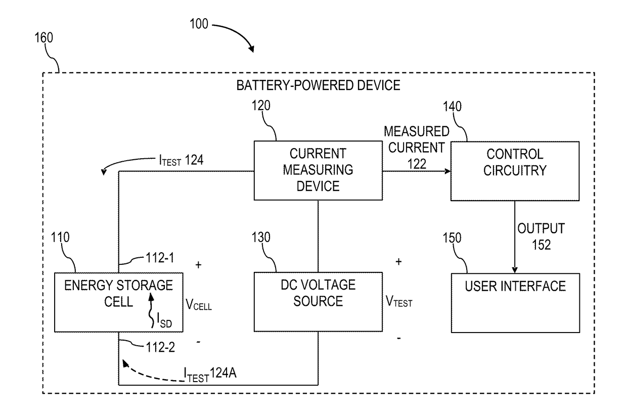
[0006]Disclosed in some embodiments herein is a method of determining a self-discharge current in an energy storage cell. The method includes applying, with a direct current (DC) voltage source, a constant test voltage to an energy storage cell. The constant test voltage is less than an open-circuit voltage of the energy storage cell at an initial state of charge (SOC) of the energy storage cell. ...

Problems solved by technology

One drawback of lithium-ion batteries, however, is their potential to catch fire and/or explode.
Heat generated from elevated self-discharge current through IHSCs may cause unpredictable catastrophic failures due to thermal runaway of the lithium-ion battery, in which the battery may smoke (emitting toxic vapors), catch fire, explode, or combinations thereof.
Aside from the safety issues resulting from these catastrophic failures in lithium-ion batteries, catastrophic failures have also resulted in large-scale recalls costing hundreds of millions of dollars and damaging provider reputations.
As size of batteries in rechargeable battery systems increases (e.g., in electric drive vehicles), or stationary storage (e.g., grid storage) the concern for catastrophic fail...

Method used


Image

  • Systems and related methods for determining self-discharge currents and internal shorts  in energy storage cells
  • Systems and related methods for determining self-discharge currents and internal shorts  in energy storage cells
  • Systems and related methods for determining self-discharge currents and internal shorts  in energy storage cells

Examples


Embodiment Construction

[0020]In the following detailed description, reference is made to the accompanying drawings, which form a part hereof, and in which is shown by way of illustration specific embodiments in which the present disclosure may be practiced. These embodiments are described in sufficient detail to enable those of ordinary skill in the art to practice the present disclosure. It should be understood, however, that the detailed description and the specific examples, while indicating examples of embodiments of the present disclosure, are given by way of illustration only and not by way of limitation. From this disclosure, various substitutions, modifications, additions rearrangements, or combinations thereof within the scope of the present disclosure may be made and will become apparent to those of ordinary skill in the art.

[0021]In accordance with common practice, the various features illustrated in the drawings may not be drawn to scale. The illustrations presented herein are not meant to be ...


PUM


Abstract

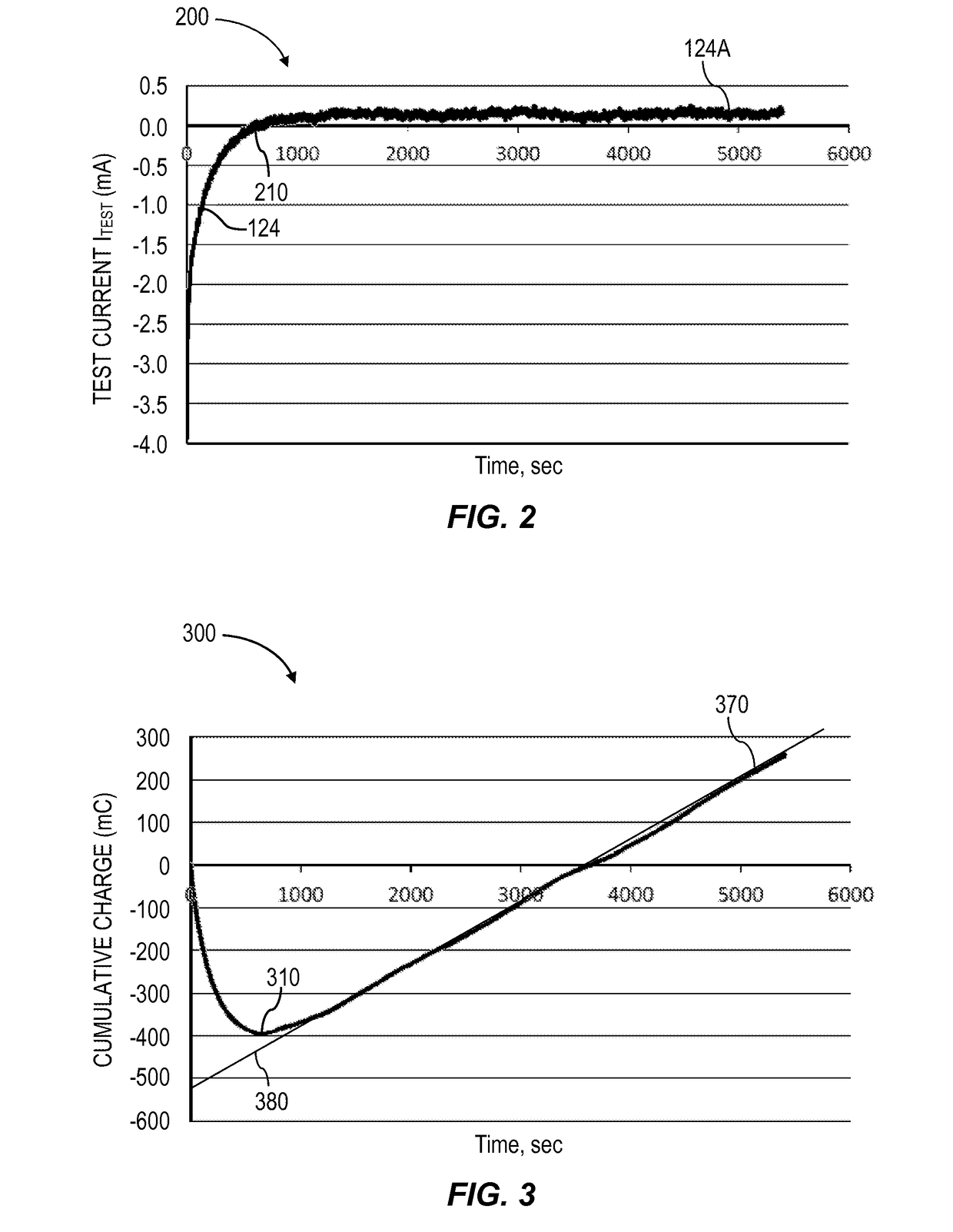
Systems and methods for determining self-discharge currents in an energy storage cell and detecting internal shorts are disclosed. A system includes a DC voltage source configured to provide a constant test voltage selected to be less than an open-circuit voltage of an energy storage cell to the energy storage cell. The system also includes a current measuring device operably coupled between the DC voltage source and the energy storage cell, and control circuitry operably coupled to the current measuring device. A method includes applying the constant test voltage, and measuring the test current flowing between the DC voltage source and the energy storage cell until after the test current switches from a negative current to a positive current. The method also includes determining a self-discharge current of the energy storage cell by analyzing the measured test current with computational models that capture physical processes tied to the test methods.

Description

STATEMENT REGARDING FEDERALLY SPONSORED RESEARCH OR DEVELOPMENT[0001]The invention was made with government support under Contract No. DE-AC07-05-ID14517, awarded by the United States Department of Energy. The government has certain rights in this invention.BACKGROUND[0002]The present disclosure relates to systems and methods for determining health parameters of energy storage cells and, more specifically, to self-discharge determination in energy storage cells (e.g., employed in rechargeable service), as well as systems including such cells.[0003]Rechargeable batteries are used in many devices, including cars and portable consumer electronics. Demand for higher and higher energy density rechargeable batteries with smaller and smaller self-discharge in these devices, among other things, has brought lithium-ion batteries to prominence (lithium-ion batteries typically have relatively high energy density and relatively low self-discharge compared to most other known battery chemistries...

Claims


Application Information

Patent Timeline
IPC IPC(8): G01R31/36G01R31/02G01R31/00
CPCG01R31/3606G01R31/003G01R31/3658G01R31/3648G01R31/025G01R31/396G01R31/52H01M10/42H01M10/425Y02E60/10G01R31/382
Inventor SAZHIN, SERGIY V.DUFEK, ERIC J.GERING, KEVIN L.
Owner BATTELLE ENERGY ALLIANCE LLC
Why Eureka
Try Eureka