Lens driving device

Active Publication Date: 2017-06-01
TDK TAIWAN
View PDF6 Cites 8 Cited by
  • Summary
  • Abstract
  • Description
  • Claims
  • Application Information

AI Technical Summary

Benefits of technology

[0007]An object of the invention is to provide a lens driving device which can reduce the shake generat

Problems solved by technology

This adversely affects the effecti

Method used


Image

  • Lens driving device
  • Lens driving device
  • Lens driving device

Examples


Embodiment Construction

[0029]A detailed description is given in the following embodiments with reference to the accompanying drawings.

[0030]In the following detailed description, the orientations of “on”, “above”, “under”, and “below” are used for representing the relationship between the relative positions of each element as illustrated in the drawings, and are not meant to limit the invention.

[0031]In addition, the present disclosure may repeat reference numerals and / or letters in the various examples. This repetition is for the purpose of simplicity and clarity and does not in itself dictate a relationship between the various embodiments and / or configurations discussed. Various features may be arbitrarily drawn in different scales for the sake of simplicity and clarity. Furthermore, some elements not shown or described in the embodiments have the forms known by persons skilled in the field of the invention.

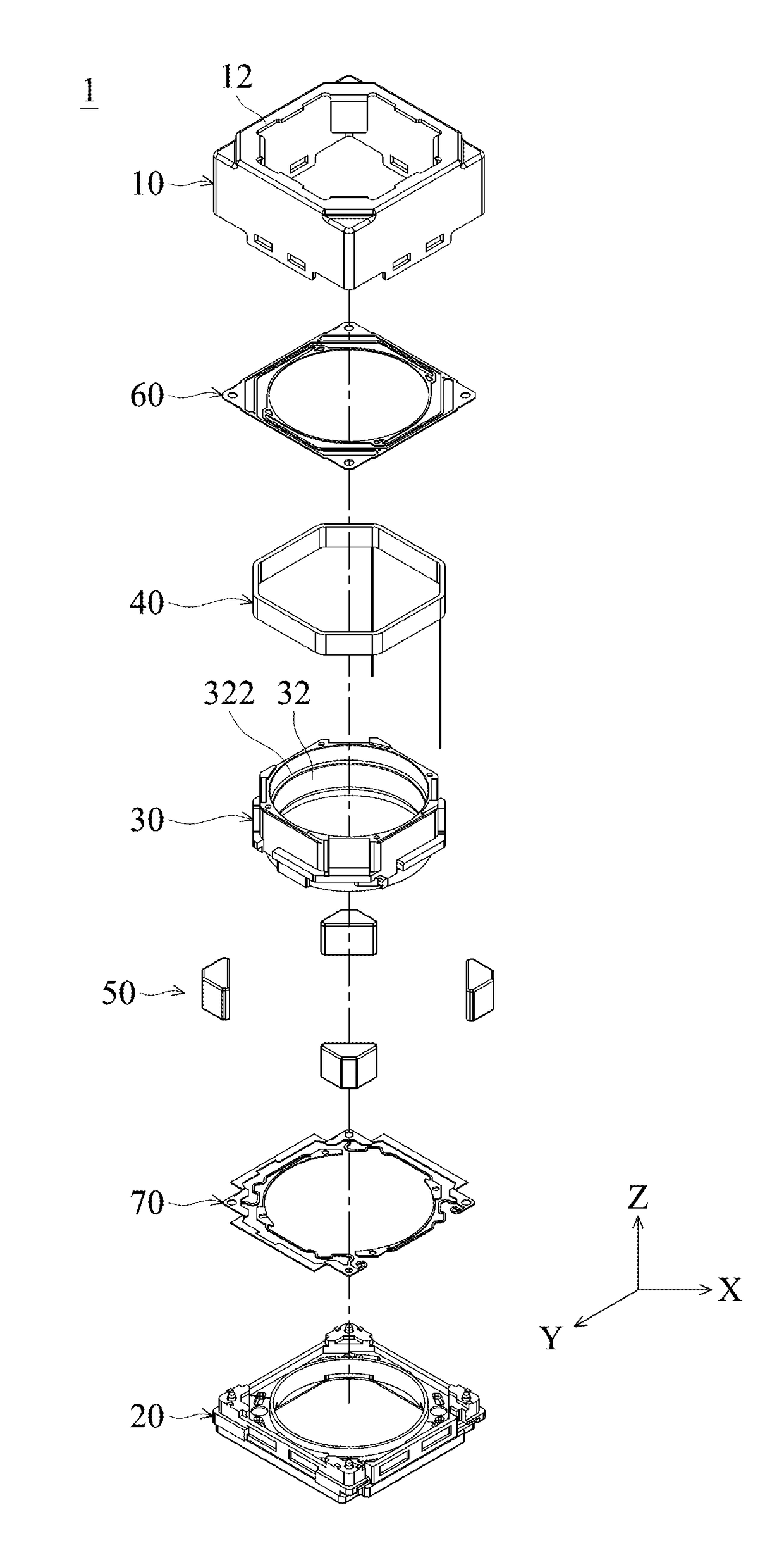
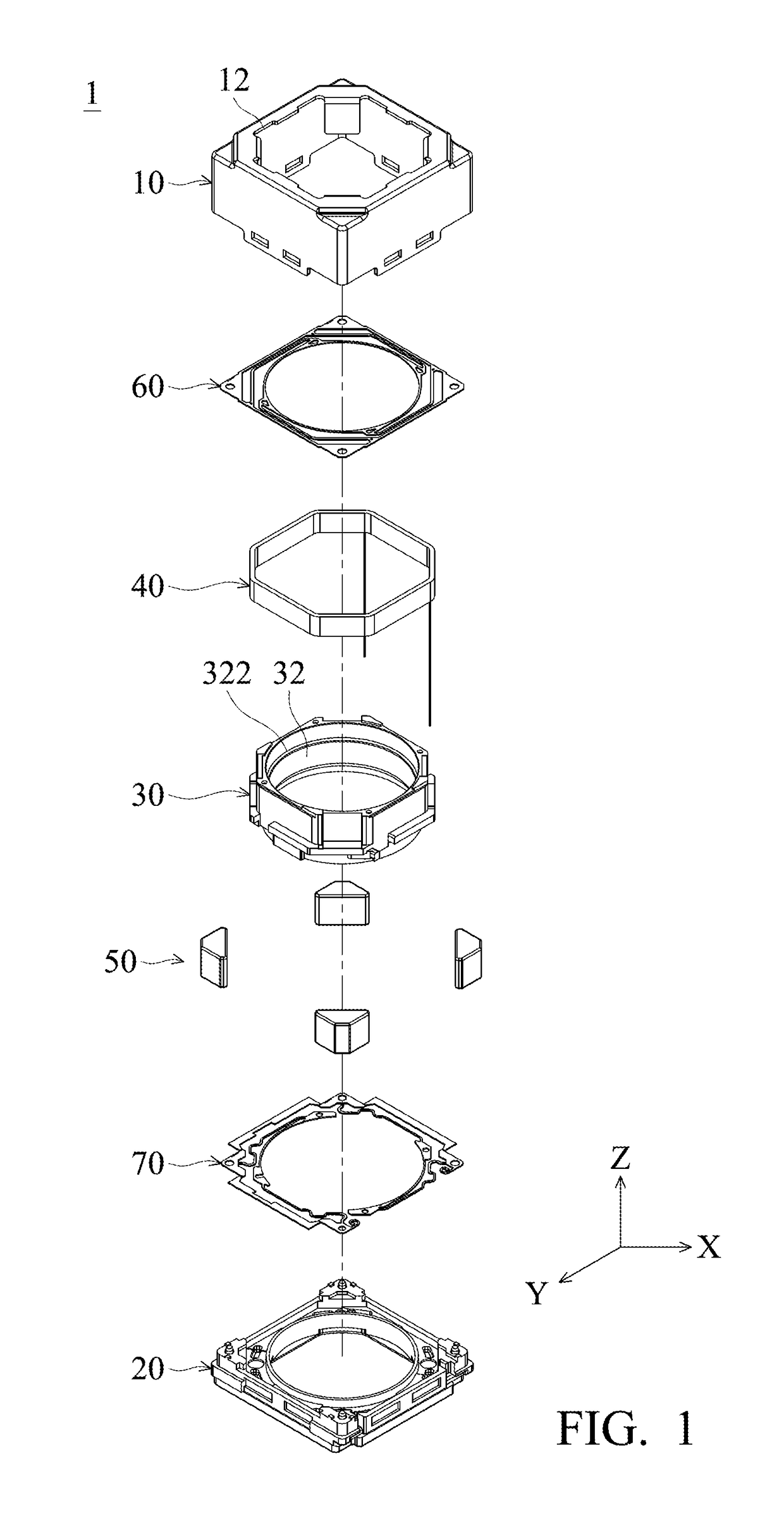
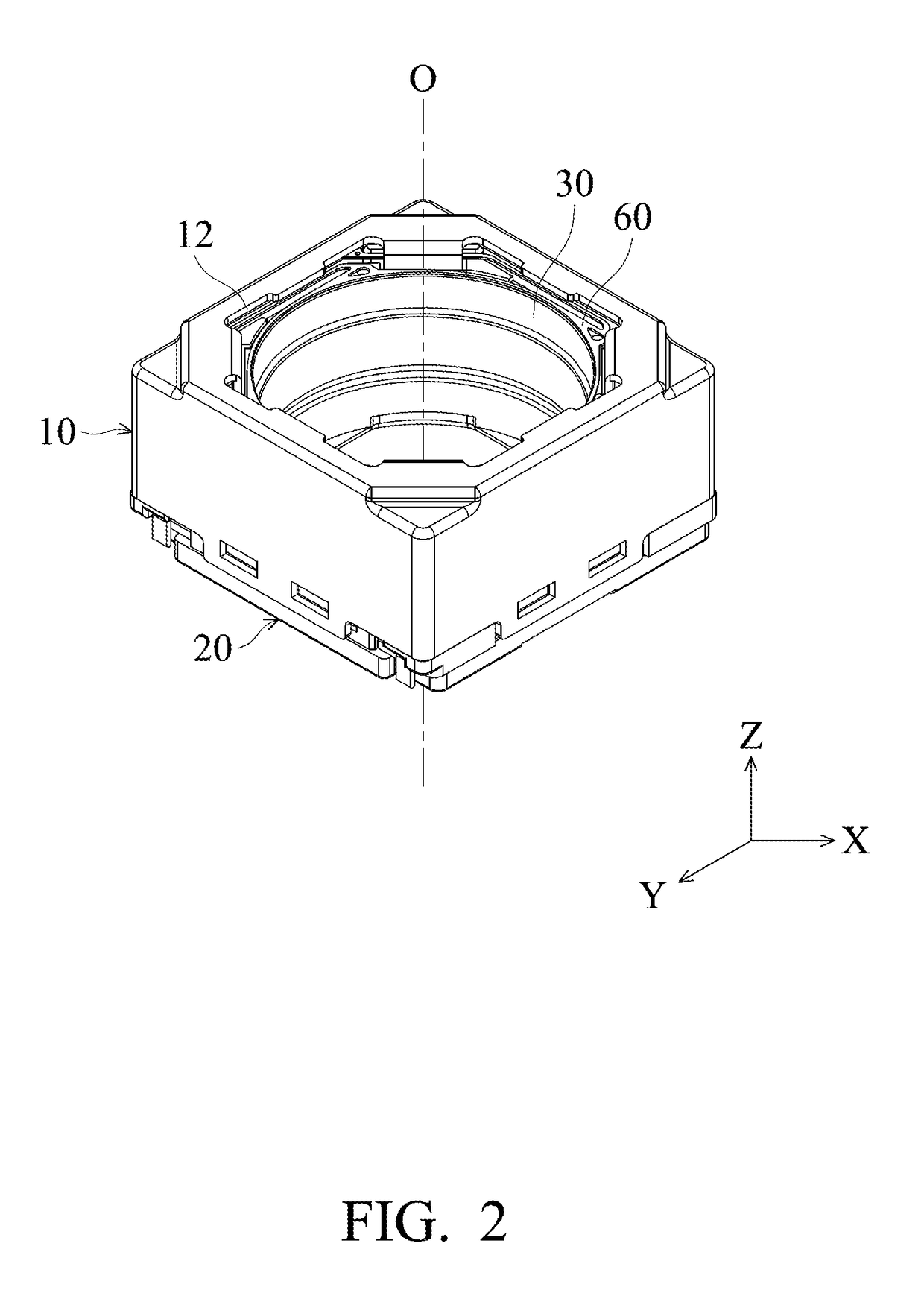
[0032]Please refer to FIG. 1 and FIG. 2, wherein FIG. 1 is an exploded view of a lens driving dev...


PUM


Abstract

A lens driving device is provided, including a frame, a lens holder, a spring sheet, and at least one damping element. The lens holder is movably disposed in the frame. The spring sheet has an outer periphery portion combined with the frame, an inner periphery portion combined with the lens holder, and an arm portion connected between the outer periphery portion and the inner periphery portion. The damping element is connected between the arm portion of the spring sheet and at least one of the frame and the lens holder.

Description

CROSS REFERENCE TO RELATED APPLICATIONS[0001]The present application claims priority of Taiwan Patent Application No. 104140047, filed on Dec. 1, 2015, the entirety of which is incorporated by reference herein.BACKGROUND OF THE INVENTION[0002]Field of the Invention[0003]The invention relates to a lens driving device, and in particular to a lens driving device which requires less focusing time.[0004]Description of the Related Art[0005]Many mobile devices such as mobile phones are equipped with digital cameras as a basic requirement nowadays, and this is only possible thanks to the miniaturization of lens driving devices. In order to provide automatic focusing or zooming, a commonly used miniature lens driving device is a Voice Coil Motor (VCM), which carries a lens and can move the lens back and forth along an image-capturing optical axis by means of a coil, a magnet, and a spring sheet.[0006]Generally, when a lens (of VCM) is moved to a fixed position to bring the subject into focus...

Claims


Application Information

Patent Timeline
IPC IPC(8): G02B7/02G03B13/36H04N5/232G02B7/09
CPCG02B7/026H04N5/23248G03B13/36G02B7/09G02B7/04G03B13/34G03B3/10G03B5/00G03B2205/0053H04N23/57H04N23/55G02B7/08G02B7/102G02B27/646
Inventor CHAN, YI LIANG
Owner TDK TAIWAN
Why Eureka
Try Eureka