
Method for producing a plurality of measurement regions on a chip, and chip having a plurality of measurement regions

a technology of measurement region and chip, which is applied in the field of microfluids, can solve the problems of reacted again for detection, difficulty in carrying out the system described, and problems in the actual measuremen

Active Publication Date: 2017-06-08
BOEHRINGER LNGELHEIM VETMEDICA GMBH
View PDF4 Cites 1 Cited by
  • Summary
  • Abstract
  • Description
  • Claims
  • Application Information

AI Technical Summary

Benefits of technology

The present invention aims to improve the fluid properties of a chip used for measuring biological samples. Specifically, the invention aims to provide a chip that can be easily functionalized with different reagents for the measurement and removal of these reagents without leaving any residue. The measurement region should also be configured to accommodate a suitable amount of reagents and can be closed. These technical improvements will allow for more efficient and accurate testing of biological samples.

Problems solved by technology

Improved results in the spotting process can in fact be achieved in this manner, although the formation of a hydrophobic monolayer on the chip leads to problems in the actual measurement, especially if the chip has to be wetted over a large area with several reagents in succession for the detection.
In particular, those reactions in which a substance, for example an antigen, is bound to the substrate, for example an antibody, bonded to the chip surface and the compound formed must then be reacted again for the detection are difficult to carry out with the system described.
Highly hydrophilic measurement regions moreover have the disadvantage that, in particular with an otherwise hydrophobic chip surface, the spotting process can indeed be carried out very precisely and cleanly, but complete removal of individual reagent or sample solutions if the chip surface is wetted several times is possible only with difficulty.
The prior art thus lacks a concrete configuration of the measurement regions in combination with suitable materials in order to ensure not only defect-free spotting of the individual measurement regions but rather also an improved and reproducible measurement on the chip.

Method used


Image

  • Method for producing a plurality of measurement regions on a chip, and chip having a plurality of measurement regions
  • Method for producing a plurality of measurement regions on a chip, and chip having a plurality of measurement regions
  • Method for producing a plurality of measurement regions on a chip, and chip having a plurality of measurement regions

Examples


Embodiment Construction

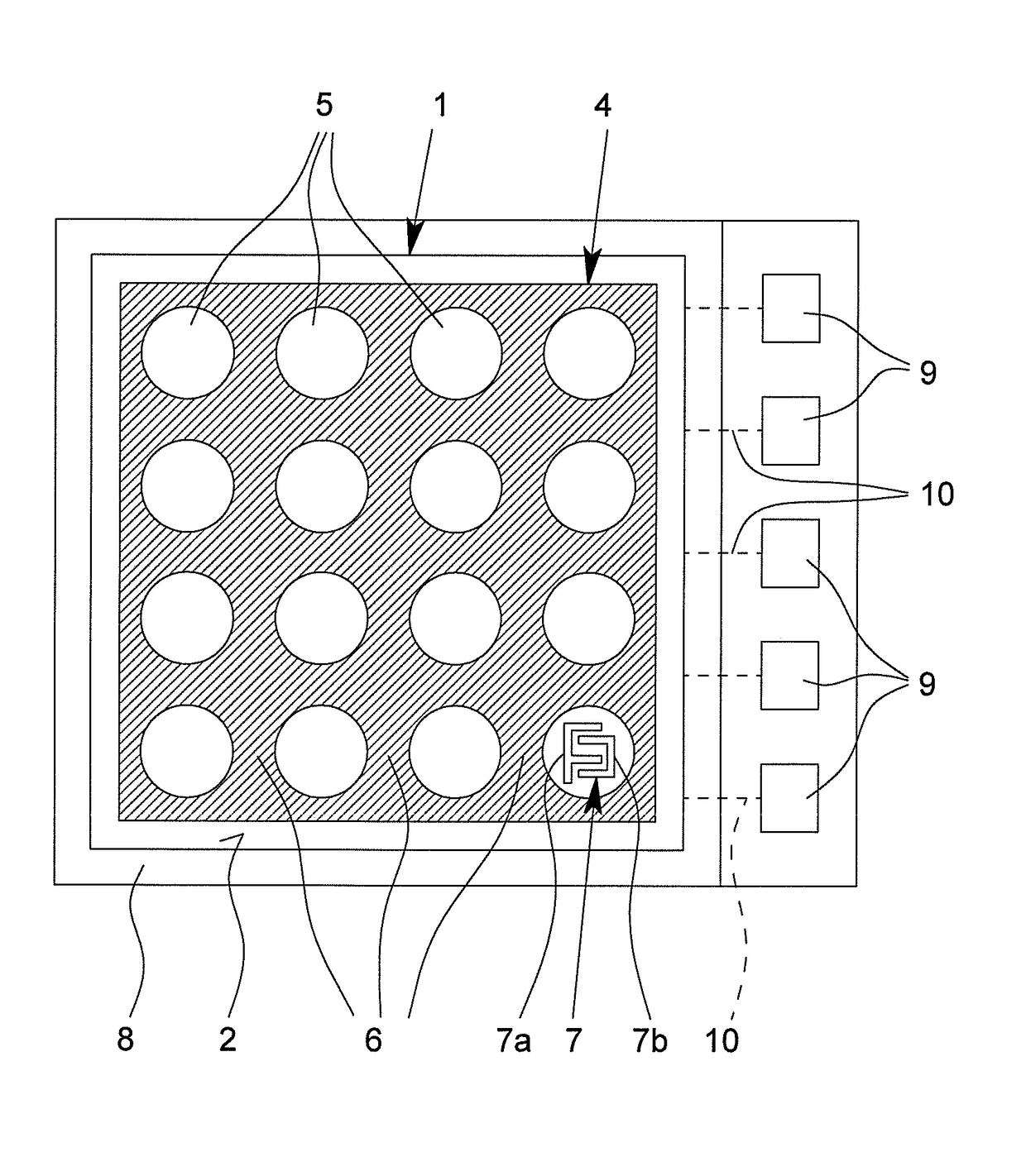
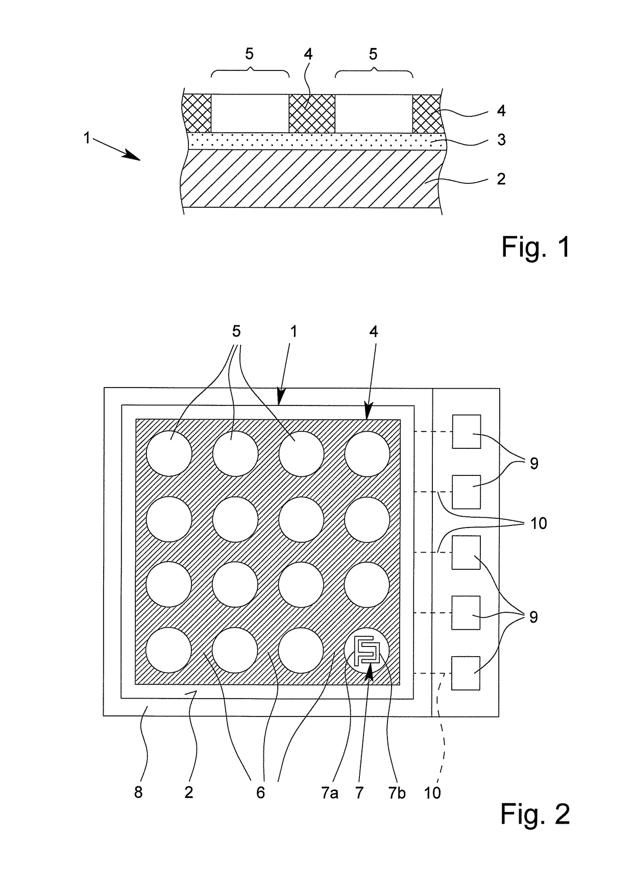
[0121]The present invention—according to a second aspect of the present invention—further provides a chip having a multiplicity of electrically addressable measurement regions, wherein a hydrophobic structure, in particular a hydrophobic layer, defining the measurement regions is provided on the chip surface, wherein the hydrophobic structure (4) is formed three-dimensionally.

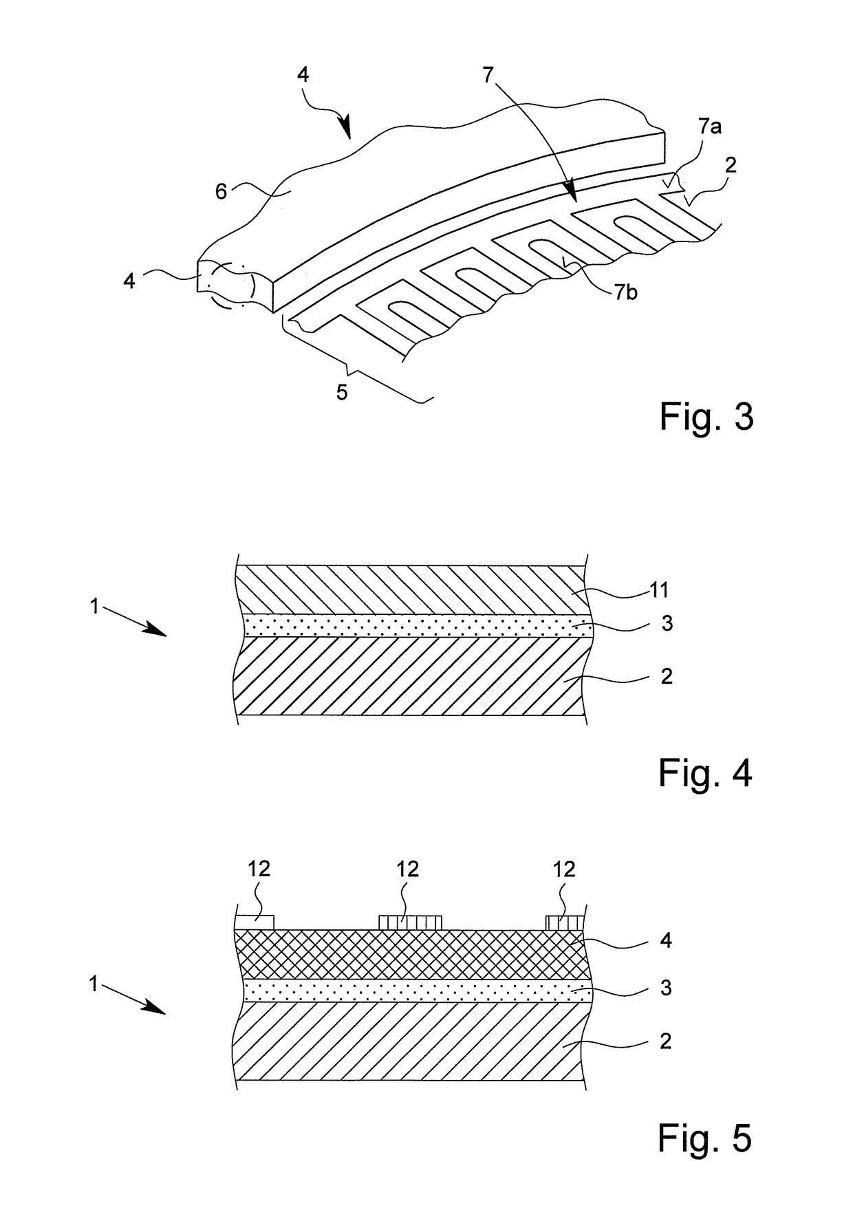
[0122]In the context of the present invention, it is preferable for the chip surface to be formed at least substantially flat and for the hydrophobic structure to be raised relative to this. The hydrophobic structure or the hydrophobic layer is thus preferably a raised structure or layer.

[0123]Chips of particular performance are obtained in the context of the present invention if the hydrophobic structure has a layer thickness of from 0.5 to 20 μm, in particular 1 to 10 μm, preferably 2 to 8 μm, more preferably 3 to 7 μm, particularly preferably 4 to 6 μm. In the context of the present invention, it is preferab...


PUM


Abstract

A method for producing a plurality of measurement regions on a chip, and a chip having a plurality of measurement regions which is obtainable by the method.

Description

BACKGROUND OF THE INVENTION[0001]Field of the Invention[0002]The present invention relates to the technical field of microfluids, in particular to microfluids in combination with semiconductor technology. In particular, the present invention relates to a method for producing a plurality of measurement regions on a chip.[0003]The present invention moreover relates to a chip having a multiplicity of electrically addressable measurement regions.[0004]Description of Related Art[0005]Microfluid systems are outstandingly suitable for carrying out chemical and biological detection reactions with low sample volumes.[0006]In the field of clinical chemistry, in particular in biological and chemical diagnostics, chip-based systems, known as microarrays, are increasingly relied upon in particular in the detection of pathogens, such as, for example, viruses. Chip-based investigation methods allow simultaneous detection of a multiplicity of chemical or biological reactions in the smallest space. ...

Claims


Application Information

Patent Timeline
IPC IPC(8): B05D3/06B05D1/28B05D1/00G01N33/543
CPCB05D3/06B05D1/005B05D1/28G01N33/54386B01L3/5085B01L3/5088B01L2300/0819B01L2300/0893B01L2300/161B01L2200/12B01L3/502707B01L3/502715B01L2300/12B01L2300/165
Inventor NIEMEYER, AXELSCHOEDER, HEINZ-ULRICHGRIESSNER, MATTHIAS
Owner BOEHRINGER LNGELHEIM VETMEDICA GMBH
Learn More