In-vehicle control apparatus

a technology for controlling apparatus and vehicles, applied in the direction of diagnostic recording/measuring, instruments, tractors, etc., can solve the problems of delay in the direction of directing the driver to the vicinity of the vehicle, and the driver may become unable to driv

Active Publication Date: 2017-06-08
DENSO CORP
View PDF6 Cites 28 Cited by
  • Summary
  • Abstract
  • Description
  • Claims
  • Application Information

AI Technical Summary

Benefits of technology

[0007]It is an object of the present disclosure to provide an in-vehicle control apparatus capable of implementing measures appropriate for safety when a driver becomes unable to drive.
[0010]In contrast, the in-vehicle control apparatus according to the example of the present disclosure determines whether a driver is unable to drive due to a sudden illness while driving. When the driver is determined to be unable to drive, the alarm annunciator is activated to issue an alarm outwardly from the vehicle before the hazard avoidance process is performed. The hazard avoidance process is not performed when the driver's manipulation stops an alarm after the alarm annunciator starts issuing the alarm outwardly from the vehicle. The hazard avoidance process is performed after a lapse of specified time from the start of the alarm on condition that the alarm is not stopped. In such a case, it is critical to avoid occurrence of an accident resulting from the driver's inability to drive if the driver is unlikely to return to normal after the driver becomes unable to drive. The above configuration issues an alarm outwardly from the vehicle in advance. This can fast alert the vicinity of the vehicle. Thus, measures appropriate for safety can be implemented when the driver is unable to drive.

Problems solved by technology

However, the driver may become unable to drive due to a sudden illness.
In such a case, measures directed to the vicinity of the vehicle may delay.

Method used


Image

  • In-vehicle control apparatus
  • In-vehicle control apparatus
  • In-vehicle control apparatus

Examples


first embodiment

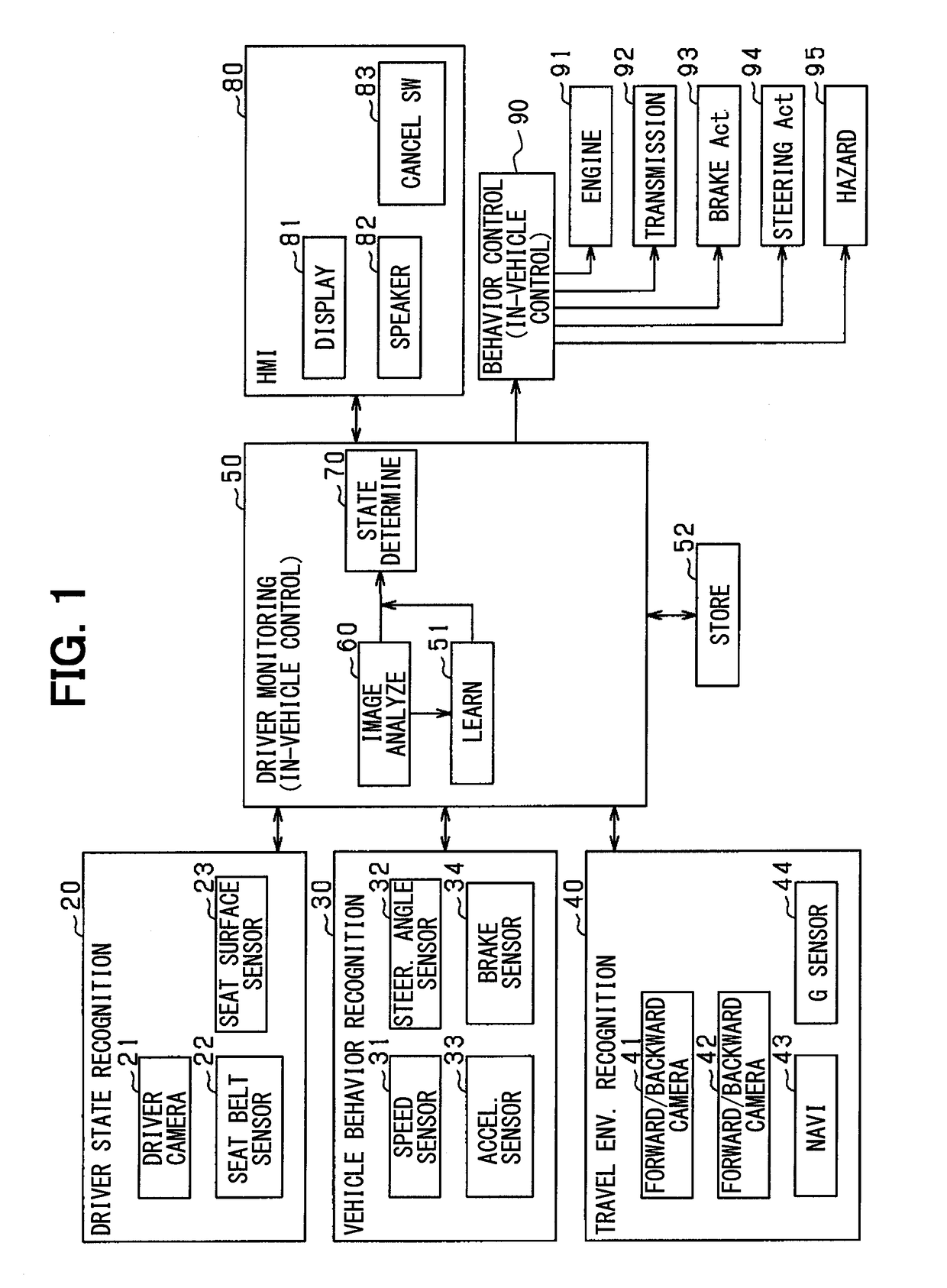
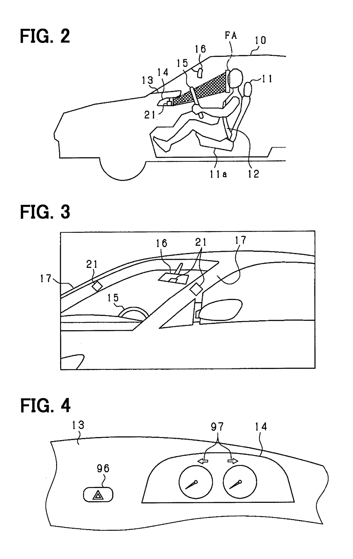
[0021]An embodiment of the present disclosure will be described with reference to the accompanying drawings. The description below explains a configuration of the in-vehicle system according to a first embodiment with reference to FIGS. 1 through 3. The system is mounted on a vehicle and includes an in-vehicle control apparatus, a driver state recognition apparatus 20, a vehicle behavior recognition apparatus 30, a travel environment recognition apparatus 40, and an HMI (Human Machine Interface) 80. The in-vehicle control apparatus includes a driver monitoring apparatus 50 and a behavior control apparatus 90. A vehicle mounted with the system is also referred to as a host vehicle or as a subject vehicle. The driver monitoring apparatus 50 determines whether the driver is under driving inability state where the driver is unable to drive, based on information from the recognition apparatuses, and notifies the HMI 80 and the behavior control apparatus 90 of a possible result of the det...

second embodiment

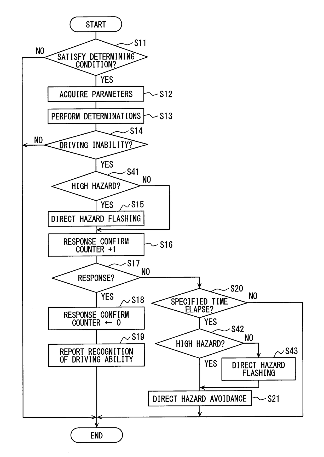
[0107]A second embodiment issues both a first alarm and a second alarm, which are issued outwardly from the vehicle. The first alarm is issued by using the hazard lamp 95 immediately after the driver is determined to be unable to drive. The second alarm is issued by the hazard lamp 95 following confirming no response from the driver after a lapse of specified time from a point to start the first alarm; the second alarm is issued in a mode more easily recognized around the host vehicle than the first alarm.

[0108]FIG. 8 is a flowchart illustrating a process according to the present embodiment. The driver monitoring apparatus 50 performs this process that replaces the process in FIG. 6. The mutually corresponding parts in FIGS. 8 and 6 are designated by the same reference symbols and a description is omitted for the purpose of illustration. In FIGS. 8, S31 and S32 are newly added.

[0109]At S11 through S14 in FIG. 8, it is determined whether the driver is unable to drive. The processing ...

third embodiment

Other Examples of Third Embodiment

[0122]The following conditions may be satisfied to select the alarm of immediately flashing the hazard lamp 95 or the alarm of confirming the driver's response and then flashing the hazard lamp 95 when the driver is determined to be unable to drive.

[0123]A vehicle speed of the vehicle 10 may be used to select the alarm of immediately flashing the hazard lamp 95 or the alarm of confirming the driver's response and then flashing the hazard lamp 95. Specifically, a vehicle speed threshold value (e.g., a specified speed ranging from 40 to 80 km / h) is predetermined. At S41 and S42 in FIG. 9, it is determined whether a speed at the determination on the driver's inability to drive is higher than or equal to the threshold value. If the vehicle speed is higher than or equal to the threshold value, the driver monitoring apparatus 50 immediately flashes the hazard lamp 95 when the driver is determined to be unable to drive (S15). If the vehicle speed is lower ...


PUM


Abstract

An in-vehicle control apparatus performs a hazard avoidance process. The in-vehicle control apparatus includes an anomaly determination section, an alarm control section, and a hazard avoidance control section. The anomaly determination section determines whether a driver is under driving inability state during travel of the vehicle, based on information on monitoring of state of the driver. The alarm control section activates an alarm annunciator to issue an alarm outwardly from the vehicle when the driver is determined to be under driving inability state. After the alarm annunciator starts the alarm, the hazard avoidance control section fails to perform the hazard avoidance process when the alarm is stopped by a manipulation of the driver and performs the hazard avoidance process when a specified time elapses under state where the alarm is not stopped since the starting of the alarm.

Description

CROSS REFERENCE TO RELATED APPLICATION[0001]The present application is based on Japanese Patent Application No. 2014-169541 filed on Aug. 22, 2014, the disclosure of which is incorporated herein by reference.TECHNICAL FIELD[0002]The present disclosure relates to an in-vehicle control apparatus.BACKGROUND ART[0003]While driving a vehicle, a sudden illness may disable a driver from recognition, decision, or manipulation needed for driving, eventually causing an accident. To solve this issue, there is proposed a technology to determine a driver anomaly such as postural imbalance. For example, a driving control apparatus described in patent literature 1 detects a pressure of driver's buttocks on a driver's seat surface, a pressure of the driver's back on a seat back, and a pressure of the driver's left foot on a floor. The driving control apparatus determines whether the driver's posture is normal, leans forward, or leans backward, based on distribution of the pressures. The driving con...

Claims


Application Information

Patent Timeline
Patent Type & Authority Applications(United States)
IPC IPC(8): B60K28/06B60N2/00G08B21/02B60W30/09B60W40/08G08G1/16B60Q1/46B60R22/48
CPCB60K28/066B60Q1/46B60N2/002B60R22/48B60W2040/0818B60W40/08G08G1/16G08B21/02B60R2022/4825B60W30/09B60Q1/525B60Q5/005B60Q9/008B60W2520/10G08B21/06G08B3/00G08B5/38G08G1/166B60W2540/215G06V20/597A61B5/18A61B5/165
Inventor MUNAOKA, YUTAKABANNO, HIROTO
Owner DENSO CORP
Why Eureka
Try Eureka