
Revolving ultrasound field multiphase flowmeter

a multi-phase flowmeter and rotating technology, applied in the direction of instruments, liquid/fluent solid measurement, volume/mass flow by differential pressure, etc., can solve the problems of unsuitable phase fraction quantification technology, difficult to accurately measure the various properties of the monitored multi-phase, and difficult to meet the requirements of oil production environmen

Inactive Publication Date: 2017-06-08
HURMUZLU YILDIRIM +1
View PDF3 Cites 3 Cited by
  • Summary
  • Abstract
  • Description
  • Claims
  • Application Information

AI Technical Summary

Benefits of technology

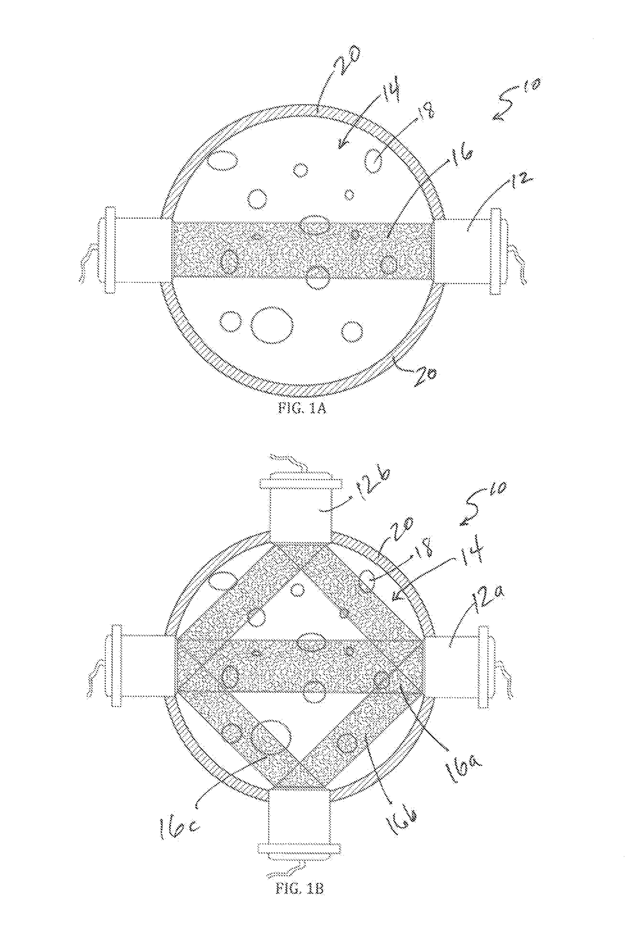
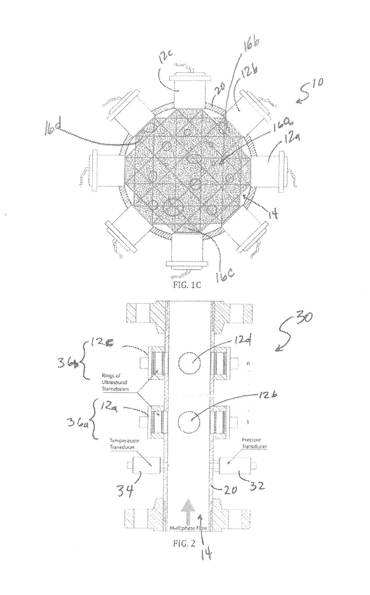
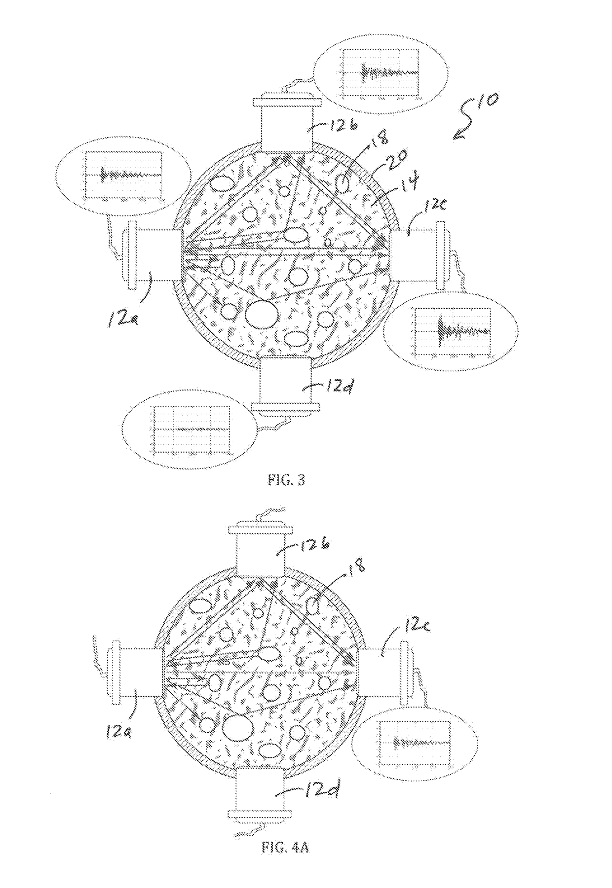
The present invention is a device and method for determining the flow of a multiphase fluid mixture. The device includes an ultrasound field detector ring with transversal paired single or multiple frequency ultrasound transmitter / receivers that are positioned in a transversal direction to the flow of the multiphase fluid mixture. The device can also include one or more ultrasound field detector rings adjacent to the first detector ring. The device can also include a computer connected to the ultrasound transmitter / receivers for calculating the phases of the multiphase fluid mixture. The device can be used to measure the flow of oil, gas, and water in a multiphase fluid mixture. The technical effects of the invention include improved accuracy in measuring the flow of multiphase fluid mixtures and the ability to detect and measure the fractions of the different phases in the mixture.

Problems solved by technology

Development of accurate and compact multiphase metering devices that can be installed at well heads in remote onshore fields and unmanned offshore platforms continues to be a technological challenge.
However, conventional devices have had difficulty in producing an accurate measurement of various properties of the monitored multiphase while withstanding the harsh environments in which such devices are typically installed.
These technologies are unsuitable to quantify phase fractions and flow rates of oil, gas, and water in a multiphase flow stream in an oil pipeline.
In particular, the field conditions of the oil production environment are extremely harsh because of high pressure and temperatures, and because of abrasive particles such as sand.
Furthermore, the presence of gas bubbles in the flow streams as well as effects due to high temperature and pressure in the pipeline require specialized models to obtain accurate data collection and analysis.

Method used


Image

  • Revolving ultrasound field multiphase flowmeter
  • Revolving ultrasound field multiphase flowmeter
  • Revolving ultrasound field multiphase flowmeter

Examples


Embodiment Construction

[0017]While the making and using of various embodiments of the present invention are discussed in detail below, it should be appreciated that the present invention provides many applicable inventive concepts that can be embodied in a wide variety of specific contexts.

[0018]The specific embodiments discussed herein are merely illustrative of specific ways to make and use the invention and do not delimit the scope of the invention.

[0019]To facilitate the understanding of this invention, a number of terms are defined below. Terms defined herein have meanings as commonly understood by a person of ordinary skill in the areas relevant to the present invention. Terms such as “a”, “an” and “the” are not intended to refer to only a singular entity, but include the general class of which a specific example may be used for illustration. The terminology herein is used to describe specific embodiments of the invention, but their usage does not delimit the invention, except as outlined in the cla...


PUM


Abstract

The present invention includes a device and method for determining the flow of one or more phases of a multiphase fluid mixture comprising: a tube, a pipe, a main body or any combinations thereof comprising an interior and an exterior, wherein the interior receives a multiphase fluid mixture for the determination of the fractions in the multiphase; a first ultrasound field detector ring comprising: two or more pairs of transversal paired dual frequency ultrasound transmitter / receivers are on the same normal plane and are positioned in a transversal direction to a flow of the multiphase fluid mixture on the exterior of the tube, pipe, or main body, wherein the sampled volume covers a part of or the whole cross-section of the flow volume; and a computer connected to the ultrasound transmitter / receivers that determines the one or more phases of a multiphase fluid mixture.

Description

CROSS-REFERENCE TO RELATED APPLICATIONS[0001]This application is a continuation application of U.S. patent application Ser. No. 14 / 862,753 filed on Sep. 23, 2015 entitled “Revolving Ultrasound Field Multiphase Flowmeter,” which is a non-provisional patent application of U.S. Provisional Application Ser. No. 62 / 164,940 filed May 21, 2015, the entire contents of which are incorporated herein by reference.TECHNICAL FIELD OF THE INVENTION[0002]The present invention relates in general to the field of flowmeters, and more particularly, to a revolving ultrasound field multiphase flowmeter.STATEMENT OF FEDERALLY FUNDED RESEARCH[0003]None.BACKGROUND OF THE INVENTION[0004]Without limiting the scope of the invention, its background is described in connection with ultrasound meters.[0005]Multiphase meters have attracted the attention of the oil production industry because of their accuracy and cost savings as opposed to analyzing discrete samples of multiphase fluid to determine fractions of oi...

Claims


Application Information

Patent Timeline
Patent Type & Authority Applications(United States)
IPC IPC(8): G01F1/74G01F1/66G01N29/036
CPCG01F1/74G01N2291/02433G01F1/662G01N29/036G01F1/667G01F1/44G01F1/66G01F1/68
Inventor HURMUZLU, YILDIRIMRICHER, EDMOND
Owner HURMUZLU YILDIRIM
Learn More