Motor-generator with multiple stator windings

a technology of motor generator and stator winding, which is applied in the direction of synchronous generators with multiple outputs, mechanical energy handling, transportation and packaging, etc., can solve the problems of large motor generator, complex, and cost prohibitiv

Active Publication Date: 2017-06-08
HAMILTON SUNDSTRAND CORP
View PDF4 Cites 9 Cited by
  • Summary
  • Abstract
  • Description
  • Claims
  • Application Information

AI Technical Summary

Problems solved by technology

Often, utilizing multiple sources of energy within a flywheel energy storage system may result in a motor-generator that is large, complex, and cost prohibitive.

Method used


Image

  • Motor-generator with multiple stator windings
  • Motor-generator with multiple stator windings
  • Motor-generator with multiple stator windings

Examples


Embodiment Construction

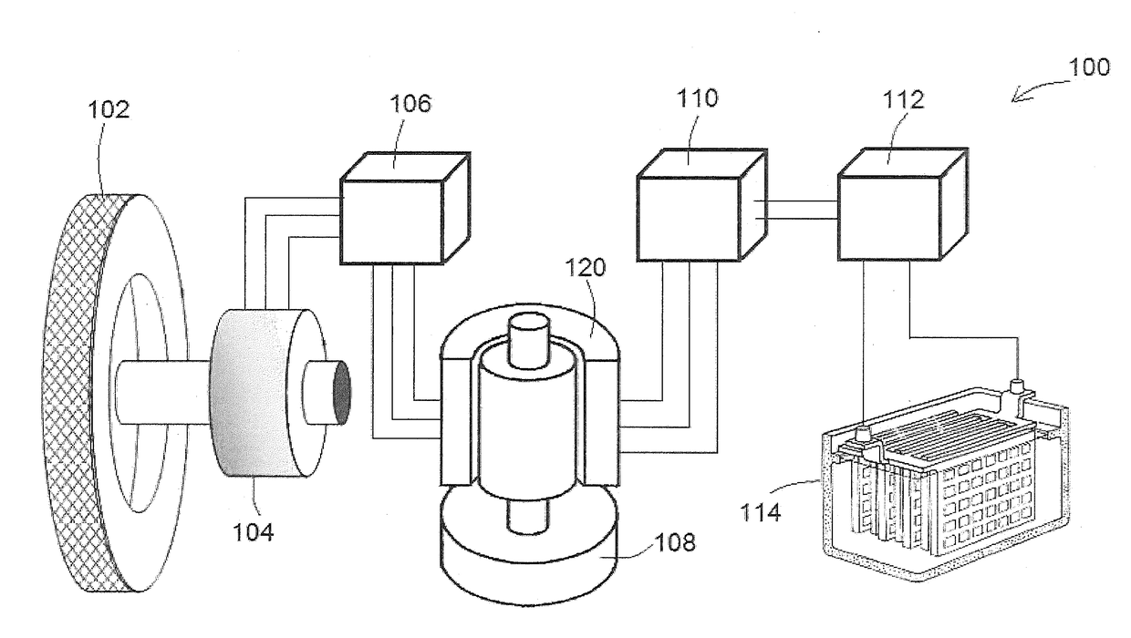
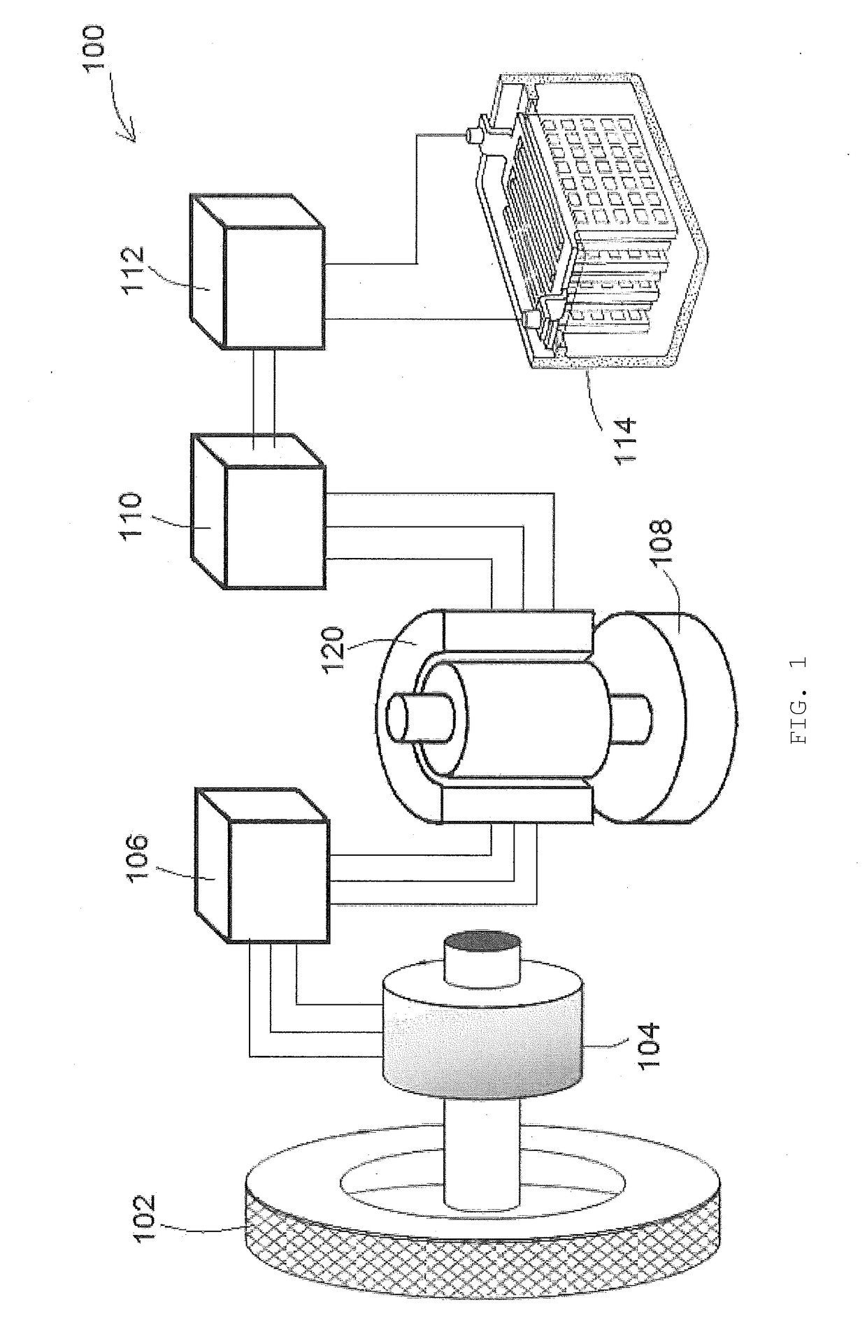
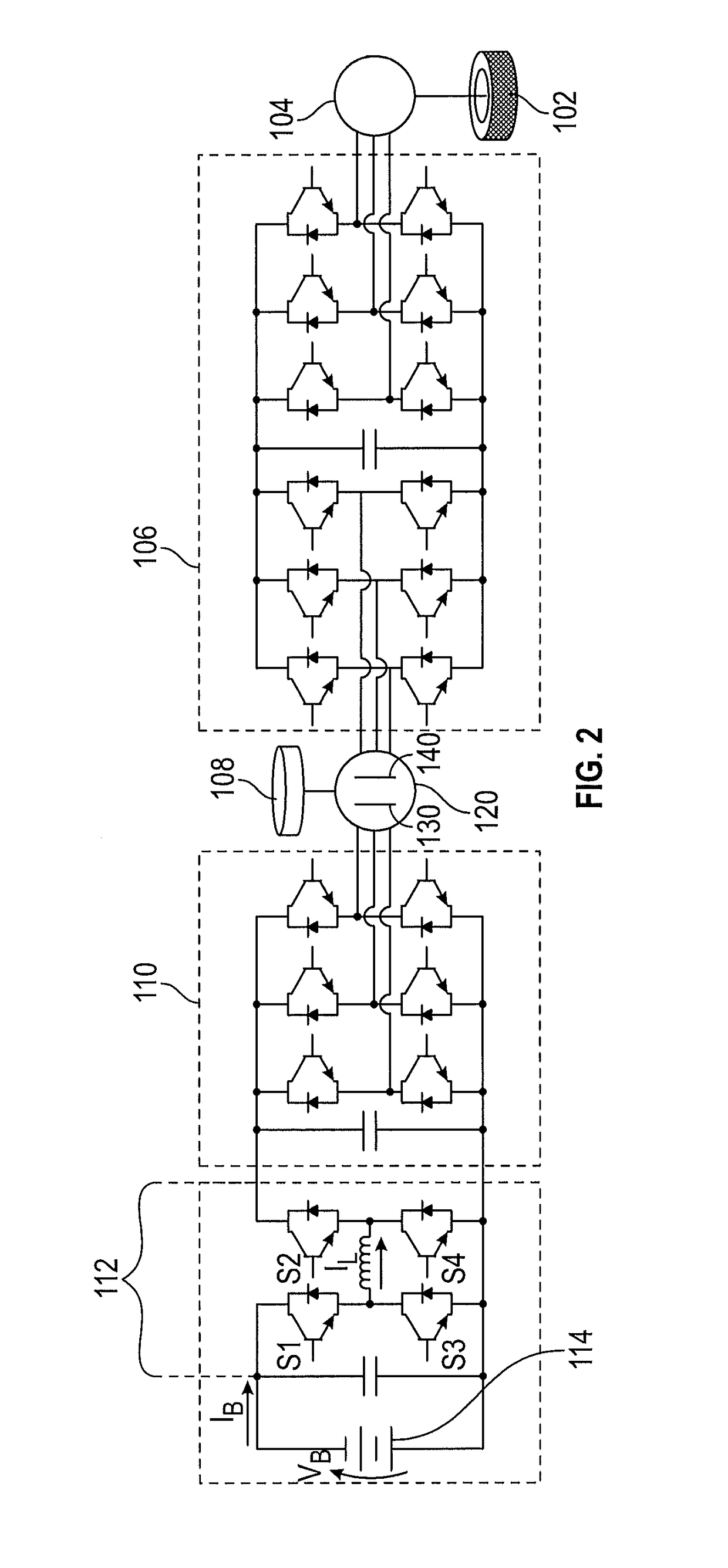
[0016]Referring now to the drawings, FIGS. 1 and 2 show an energy storage system 100. In the illustrated embodiment, the energy storage system 100 includes a wheel 102, a motor 104, a motor-generator 120, a flywheel 108, and a battery 114. In the illustrated embodiment, the energy storage system 100 can store energy from the wheel 102 and the battery 114, and release energy to the wheel 102 and the battery 114 to serve as an energy buffer to meet peak energy requirements. Advantageously, the energy storage system 100 can be used with vehicles to efficiently store and use energy and increase the battery life of the battery 114.

[0017]In the illustrated embodiment, the energy storage system 100 can provide and receive kinetic energy from the wheel 102. In other embodiments, the wheel 102 can be representative of any load that can provide and receive kinetic energy from the energy storage system 100. In the illustrated embodiment, the wheel 102 is driven by a wheel motor 104. Further, t...


PUM


Abstract

A motor-generator includes a stator disposed along a centerline including a stator pole, a first stator winding and a second stator winding, wherein the first stator winding is wound on the stator pole and the second stator winding is wound on the stator pole, and at least one rotor axially disposed from the stator along the centerline.

Description

BACKGROUND[0001]The subject matter disclosed herein relates to motor-generators, and more particularly, to a motor-generator with a stator with multiple stator windings.[0002]Flywheel energy storage systems can be used to store energy that may be typically wasted and release energy as needed. Flywheel energy storage systems may utilize supplemental energy storage to increase functionality of the storage system. Often, utilizing multiple sources of energy within a flywheel energy storage system may result in a motor-generator that is large, complex, and cost prohibitive.BRIEF SUMMARY[0003]According to an embodiment, a motor-generator includes a stator disposed along a centerline including a stator pole, a first stator winding and a second stator winding, wherein the first stator winding is wound on the stator pole and the second stator winding is wound on the stator pole, and at least one rotor axially disposed from the stator along the centerline.[0004]According to an embodiment, an...

Claims


Application Information

Patent Timeline
Patent Type & Authority Applications(United States)
IPC IPC(8): H02K3/28H02K7/02H02K47/20
CPCH02K3/28H02K7/025H02K47/20Y02E60/16H02K21/24H02K16/00H02K21/48B60K6/00
Inventor GIERAS, JACEK F.ROZMAN, GREGORY I.
Owner HAMILTON SUNDSTRAND CORP
Why Eureka
Try Eureka