Reactor device for reaction fluid

a technology of reaction fluid and reactor device, which is applied in the direction of chemical/physical/physical-chemical stationary reactors, chemical apparatus and processes, chemical/physical/physical-chemical processes, etc., can solve the problems of poor temperature control, variations in reactant concentration, poor performance of batch reactors, etc., and achieve the effect of protecting from accidental damag

Inactive Publication Date: 2017-06-15
BLACKTRACE HLDG
View PDF3 Cites 13 Cited by
  • Summary
  • Abstract
  • Description
  • Claims
  • Application Information

AI Technical Summary

Benefits of technology

[0041]Preferably, the manifold from the first reactor device is locatable between the end cap of the first reactor device and the end ca

Problems solved by technology

The large reactant volume of batch reactors, typically 1 litre-1000 litres, and relatively limited area for heat exchange, results in poor temperature control when running exothermic and endothermic reactions.
In addition mixing performance in batch reactors is poor resulting in variations in reactant concen

Method used


Image

  • Reactor device for reaction fluid
  • Reactor device for reaction fluid
  • Reactor device for reaction fluid

Examples


Embodiment Construction

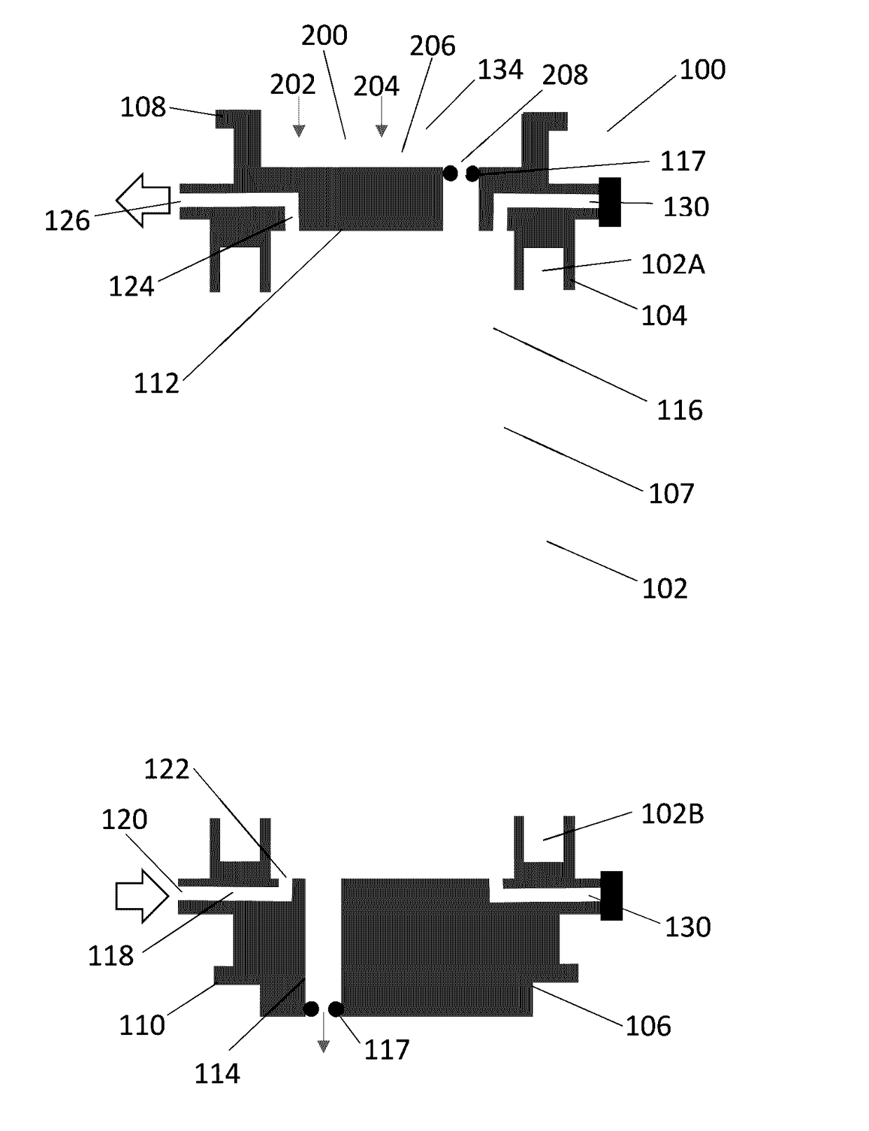
[0061]With reference to FIG. 5, there is shown a reactor device 100. The device 100 is formed of a generally cylindrical reaction vessel 102 that has an open first end 102A and an open second end 102B. The first open end 102A is closed off by a top end cap 104, and the second end 102B is closed off by a bottom end cap 106. Together the reaction vessel 102 and the two end caps 104;106 define a space 107 for the receipt of a preheated / precooled control fluid.

[0062]The reaction vessel 102 is preferably made of glass ora chemically resistant metal / metal alloy. Each of the top cap 104 and the bottom cap 106 is predominately made of a material(s) with good thermal conductivity, such as metal (for example stainless steel or aluminium). In this way, when the device is used, the end caps 104;106 are heated / cooled towards the temperature of the control fluid inside the space 107.

[0063]A respective flange 108:110 extends around the circumference of the top and bottom end cap 104;106. In use th...


PUM


Abstract

A reactor device (100) for reaction fluid comprising a reaction vessel (102) comprising: an end cap (104) comprising at least one passage (112) for the reaction fluid; and at least one tube (116) which extends through the reaction vessel (102). The reaction vessel is operable to receive a control fluid outside the at least one tube (116) for controlling the temperature inside the at least one tube (116). A manifold (200) is connectable to the end cap (104) and comprises at least one channel (206) for reaction fluid. An outlet (208) from the manifold (200) is in fluid communication with the tube (116). The end cap (104) has a thermal conductivity of greater than 1 watt per square meter kelvin to provide a thermal coupling between the control fluid and the manifold (200).

Description

[0001]The present invention relates to a reactor device for reaction fluid.BACKGROUND RELATING TO THE PRIOR ART[0002]Traditionally, large scale chemical reactions are carried out as batch processes, typically using stirred tank reactors as shown in FIG. 1, where the reactants 4 are mixed by a rotary stirrer 1 and the temperature is controlled by an outer jacket 2 with a thermofluid 3 circulating through the jacket. The large reactant volume of batch reactors, typically 1 litre-1000 litres, and relatively limited area for heat exchange, results in poor temperature control when running exothermic and endothermic reactions. In addition mixing performance in batch reactors is poor resulting in variations in reactant concentration, in particular during reactant addition.[0003]An alternative to a batch reaction process is to use a flow reactor. An example flow reactor is shown in FIG. 2 which consists of a junction 7 for combining the reactants, a pipe or channel 6 through which the react...

Claims


Application Information

Patent Timeline
IPC IPC(8): B01J19/24B01J19/00
CPCB01J19/2415B01J19/243B01J2219/24B01J2219/00085B01J19/0013B01J19/242B01J2219/00063B01J2219/00094B01J19/006B01J19/0093B01J2219/00772B01J2219/00792
Inventor HOMEWOOD, PHILIPGILLIGAN, MARKLOVATT, ANDREWCRISP, PAULTAYLOR, BENKENYON, HANNAHHAWES, MIKE
Owner BLACKTRACE HLDG
Why Eureka
Try Eureka