Work Vehicle

a technology for working vehicles and vehicles, applied in the field of work vehicles, can solve the problems of reducing the service life of the vehicle, so as to improve service life and prevent poor or degraded connections. , the effect of excellent durability

Active Publication Date: 2017-06-15
KUBOTA LTD
View PDF0 Cites 7 Cited by
  • Summary
  • Abstract
  • Description
  • Claims
  • Application Information

AI Technical Summary

Benefits of technology

[0058]Particularly in a work vehicle that does not have a cabin, in order to prevent poor or degraded connections due to penetration of rain water, dust, or the like, it is preferable that the electrical connection port has a waterproof/dustproof function. According to this configuration, the electrical connection port is covered by a cover, so that it is difficult for rain water, dust, or the like to enter, and the electrical connection port is protected from sun exposure, so that the electrical connection port has excellent durability. Further, because the cover is provided and the electrical connection port can be used outside, this configuration can also be easily utilized in a work vehicle that is not provided with a cabin, a sunshade cover, or the like.
[0059]Also, in the above configuration, it is preferable that the operator seat includes a backrest portion and a seat portion, and the electrical connection port is provided in a thick portion in a side portion of the backrest portion. According to this configuration, the electrical connection port is provided in a thick portion in a side portion of the backrest portion, so that the electrical connection port does not become a nuisance

Problems solved by technology

However, operation of the fuel switching cock as necessary places a burden on a vehicle operator.
However, because selective connection of grass collection containers having different weights to the body frame is not considered, in a case of switching from a light grass collection container to a heavy grass collection container, it is necessary to switch the weight installed to the front weight installation means to another weight that is heavier.
Therefore, the front weight installatio

Method used


Image

  • Work Vehicle
  • Work Vehicle
  • Work Vehicle

Examples


first embodiment

Basic Configuration of Fuel Circulation

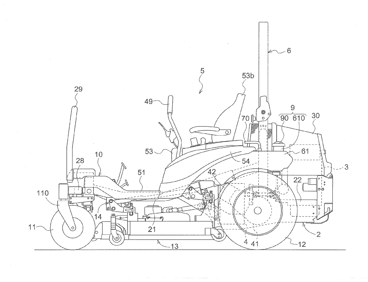
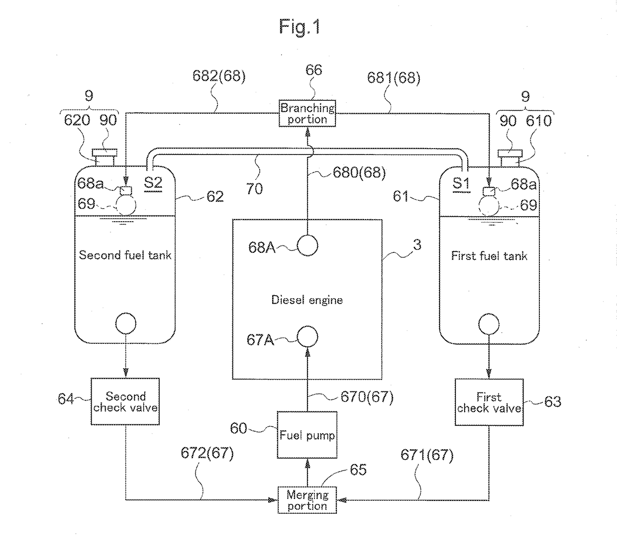
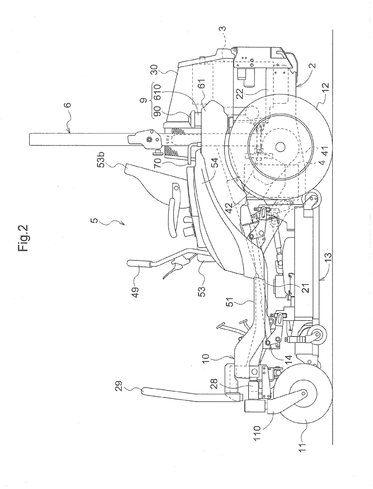
[0082]Before describing a specific embodiment of a work vehicle according to the present invention, the specific configuration of fuel circulation between fuel tanks and an engine adopted in the present invention will be described with reference to FIG. 1. An engine 3 installed in this work vehicle receives fuel supply from a left-right pair of a first fuel tank 61 and a second fuel tank 62. The first fuel tank 61 and the second fuel tank 62 have shapes that are substantially approximately the same, but the fuel tanks are not required to have the same shape. The first fuel tank 61 and the second fuel tank 62 are connected to a fuel supply port 67A of the engine 3 by a fuel supply path 67 that is typically configured with a fuel hose. The fuel supply path 67 includes a first fuel supply path 671 that connects the first fuel tank 61 to a merging portion 65, a second fuel supply path 672 that connects the second fuel tank 62 to the merging portion...

second embodiment

Overall Configuration of the Mower

[0099]In this embodiment, a mid-mount riding mower is described as a mower that is one example of a work vehicle.

[0100]FIG. 5 is a perspective view of the mower, FIG. 6 is a side view, FIG. 7 is a plan view, and FIG. 8 is a perspective view that schematically shows the front wheels area of the vehicle.

[0101]As shown in FIG. 8, the body frame 110 of the mower traveling vehicle includes a left frame 110a and a right frame 110b that extend in the front-rear direction of the vehicle and are connected to each other by a cross-beam. In the front area of the body frame 110, a left front wheel 111a and a right front wheel 111b that are freely-turning caster-type wheels are provided; and in the center area of the body frame 110, a left rear wheel 112a and a right rear wheel 112b that are drive wheels are provided. When it is not particularly necessary to distinguish between the left front wheel 111a and the right front wheel 111b, these wheels 111a, 111b wil...

third embodiment

[0120]This embodiment will be described with reference to a riding electric zero-turn mower (referred to below as simply a mower) that is one example of a work vehicle.

Overall Configuration of the Mower

[0121]FIG. 16 is a perspective view showing the overall configuration of the mower. As shown in FIG. 16, the mower includes a vehicle body 210 supportable by caster wheel units 203 that are front wheels and drive wheel units 202 that are rear wheels, an operator seat 211 disposed in the vehicle body 210, a rollover protection frame 212 provided standing to the rear of the operator seat 211, and a mower unit 213 suspended from the vehicle body 210 so as to be capable of raising / lowering through a raising / lowering linking mechanism in a space below the vehicle body 210 between the caster wheel units 203 and the drive wheel units 202.

[0122]On both sides of the operator seat 211, operation units 201 are disposed that include a left operation lever 201a and a right operation lever 201b tha...


PUM


Abstract

In a work vehicle, a fuel supply path including a first fuel supply path connecting a first fuel tank to a merging portion, a second fuel supply path connecting a second fuel tank to the merging portion, and a common supply path connecting the merging portion to an engine is formed. A fuel pump supplying fuel to the engine is provided in the common supply path. Check valves that open according to a differential pressure between pressures on the fuel tank side and the merging portion side are interposed on the first fuel supply path and the second fuel supply path. A communication channel establishes communication between an upper space of the first fuel tank and an upper space of the second fuel tank is formed.

Description

CROSS-REFERENCE TO RELATED APPLICATIONS[0001]This application claims priority to Japanese Patent Application Nos. 2015-242222, 2015-252593, and 2016-023757, filed Dec. 11, 2015, Dec. 24, 2015, and Feb. 10, 2016, respectively, the disclosures of which are hereby incorporated in their entirety by reference.BACKGROUND OF THE INVENTION[0002]Field of the Invention[0003]The present invention relates to a work vehicle such as a mower.[0004]Description of Related Art(1) First Related Art[0005]A certain kind of work vehicle mounts an engine that has its fuel supplied from a plurality of fuel tanks (for example, see JP 2563729 Y). In a fuel tank system in an agricultural tractor disclosed in JP 2563729 Y, upper portions of a right side fuel tank and a left side fuel tank are in communication with each other through an air circulation pipe, and bottom portions of the right side fuel tank and the left side fuel tank are connected to each other through a fuel withdrawal pipe, and a pump suction ...

Claims


Application Information

Patent Timeline
IPC IPC(8): B60K15/01F02M37/04B60N2/38F02M37/00
CPCB60K15/013F02M37/0023F02M37/0088B60K2015/03138F02M37/0017F02M37/007B60N2/38F02M37/04B60K2015/03118B60K2015/03144B60K15/03B60Y2200/223B60K2015/03243B62D37/04
Inventor ASAHARA, MASATOSENDA, RYOTAROYOSHIDA, SEIYAAOKI, HIDEKIUEMOTO, KENSUKETOGOSHI, YOSHIKAZUFUJII, YUTO
Owner KUBOTA LTD
Why Eureka
Try Eureka