Efem

a technology of efem and efem, which is applied in the direction of conveying devices, electrical devices, transportation and packaging, etc., can solve the problems of contamination of the wafer surface before or after the processing to be housed in the container, and achieve the effect of effectively discharging outgas and efficiently discharging outgas in the entire container

Active Publication Date: 2017-06-15
TDK CORPARATION
View PDF5 Cites 17 Cited by
  • Summary
  • Abstract
  • Description
  • Claims
  • Application Information

AI Technical Summary

Benefits of technology

[0032]The EFEM has the container inner nozzle, and thus can more effectively discharge the outgas generated from the wafer to the outside of the ...

Problems solved by technology

In the course of development for an EFEM maintaining a clean environment of the wafer container, it turned out that there is a problem that the wafer surface before or after proces...

Method used


Image

  • Efem
  • Efem
  • Efem

Examples


first embodiment

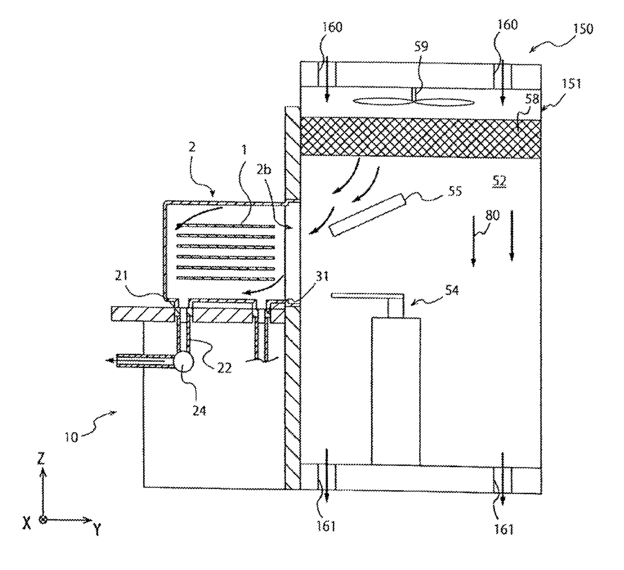
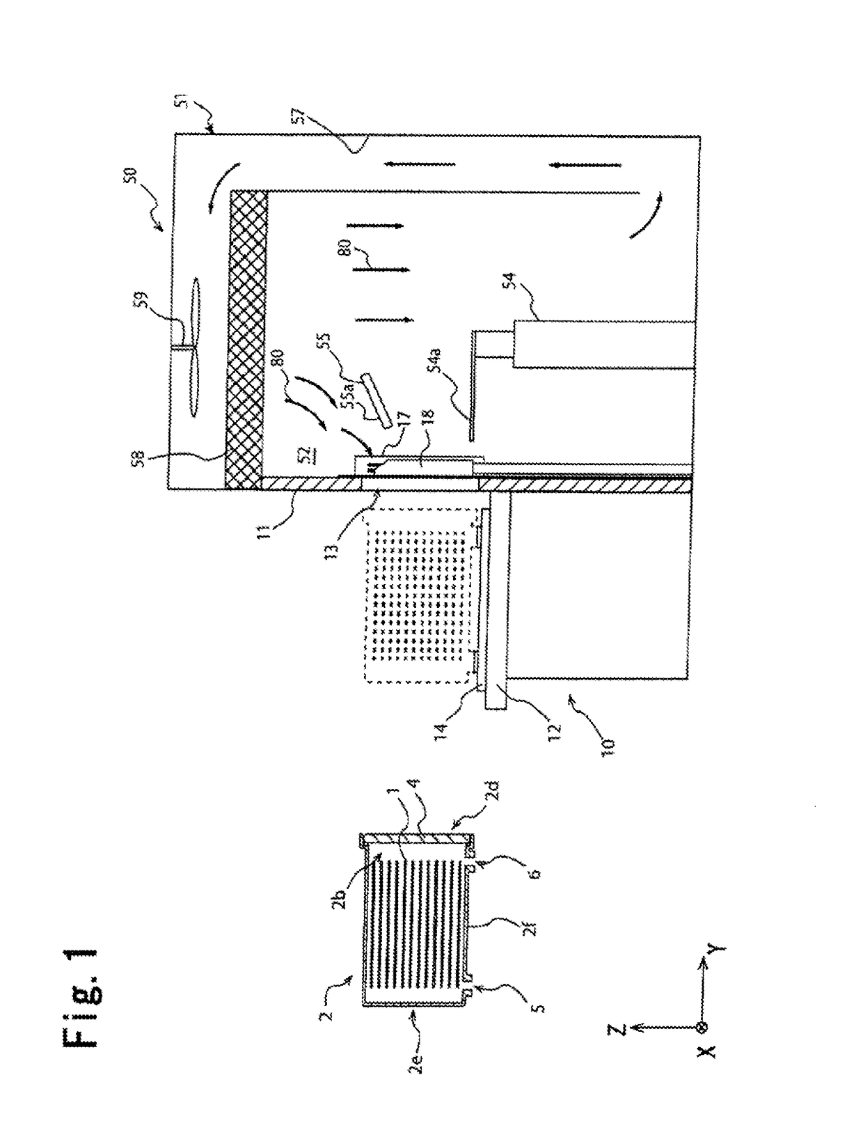
[0098]In a second cleaning step of the EFEM 150 shown in FIG. 6, an air or an inert gas is introduced from the introduction ports 160 arranged over the transportation room 52. The air or inert gas introduced above the wafer transportation room 52 passes through the transportation room filter 58, flows into the wafer transportation room 52, and is thereafter discharged from the discharge ports 161 arranged below the wafer transportation room 52. A downward current by the transportation room fan 59 is also formed in the wafer transportation room 52 of the EFEM 150 in the same manner as First Embodiment shown in FIG. 1. The second cleaning step in the EFEM 150 shown in FIG. 6 demonstrates the same effect as the EFEM 50 shown in FIG. 1 by introducing a part of the downward current 80 into the FOUP 2 using the current plate 55 and further carrying out a cleaning step of the FOUP 2 for discharging the gas in the FOUP 2 from the first bottom nozzles 21.

third embodiment

[0099]FIG. 7 is a schematic cross sectional view showing an EFEM 250 of the present invention. The EFEM 250 is the same as the EFEM 50 shown in FIG. 1 except that a wafer transportation part 251 has a transportation room blow nozzle 262 as a gas discharge means in addition to the current plate 55. The transportation room blow nozzle 262 is arranged in the wafer transportation room 52 and blows a cleaning gas from the wafer transportation room 52 toward the main opening 2b of the FOUP 2.

[0100]A cleaning gas is supplied from a pipe part not shown to the transportation room blow nozzle 262. The cleaning gas blown from the transportation room blow nozzle 262 may be an inert gas, a clean air, or the like in the same manner as the cleaning gas blown from the second bottom nozzles 31, but preferably has a higher cleanliness than that of a gas in the wafer transportation room 52 constituting the downward current 80.

[0101]In the EFEM 250 shown in FIG. 7, the wafer transportation part 251 ha...

fourth embodiment

[0102]FIG. 8 is a schematic cross sectional view showing an EFEM 350 of the present invention. The EFEM 350 is the same as the EFEM 50 shown in FIG. 1 except that a wafer transportation part 351 has a blow nozzle integrated current plate 363 instead of the current plate 55. As is the case with the current plate 55 shown in FIG. 1, the blow nozzle integrated current plate 363 is arranged near the delivery port 13 in the wafer transportation room 52 and introduces a part of a downward current formed in the wafer transportation room 52 into the FOUP 2 by an inclined surface 363a in the second cleaning step.

[0103]A plurality of blow nozzles 363b is formed on the inclined surface 363a of the blow nozzle integrated current plate 363, and a cleaning gas is blown from the blow nozzles 363b toward the main opening 2b of the FOUP 2. The cleaning gas is supplied from a pipe part not shown to the blow nozzles 363b. The cleaning gas blown from the blow nozzles 363b is the same as the cleaning g...


PUM


Abstract

An EFEM includes a wafer transportation part having a wafer transportation room passed by a wafer transported to a processing room and a load port part airtightly connecting a main opening formed on a container housing the wafer to the room. The transportation part includes a downward current forming device for forming a downward current in the room and a current plate arranged in the room and partly introducing the current into the container connected to the room via the opening. The load port part includes an installation stand for installing the container, a bottom nozzle for communicating with a bottom hole formed at a position distant from the opening more than a bottom surface middle on a bottom surface of the container, and a gas discharge passage for discharging a gas in the container to an outside thereof via the nozzle.

Description

BACKGROUND OF THE INVENTION[0001]1. Field of the Invention[0002]The present invention relates to an EFEM, and more specifically relates to an EFEM including a wafer transportation part with a wafer transportation room and a load port part.[0003]2. Description of the Related Art[0004]In manufacturing steps of semiconductors, wafers are transported between respective processing apparatuses using a container called a FOUP or so. When the wafers are processed, the wafers in the container are transported from a FOUP to a processing room via an Equipment Front End Module (EFEM) equipped with the respective processing apparatuses.[0005]In the environment of a container housing wafers, it is preferred to maintain an inactive state and a cleanliness that exceed a predetermined level so as to protect the surfaces of the wafers from oxidation and contamination. As a method for improving an inactive state and a cleanliness of a gas in the transportation container, Patent Document 1 proposes a l...

Claims


Application Information

Patent Timeline
IPC IPC(8): H01L21/673H01L21/02
CPCH01L21/67353B65G2201/0297H01L21/02046H01L21/67389H01L21/67393H01L21/67778H01L21/67781H01L21/67017H01L21/67772H01L21/67775
Inventor OKABE, TSUTOMUHORIBE, HIDETOSHI
Owner TDK CORPARATION
Why Eureka
Try Eureka