Controling method for a wafer transportation part and a load port part on an efem

Active Publication Date: 2017-06-15
TDK CORPARATION
View PDF4 Cites 8 Cited by
  • Summary
  • Abstract
  • Description
  • Claims
  • Application Information

AI Technical Summary

Benefits of technology

[0022]The bottom hole configured to discharge the gas in the container is arranged at a position distant from the main opening, and a current from the main opening to the bottom hole is thus

Problems solved by technology

In the course of development for an EFEM maintaining a clean environment of the wafer container, it turned out that there is a problem that the wafer surface before or after proces

Method used


Image

  • Controling method for a wafer transportation part and a load port part on an efem
  • Controling method for a wafer transportation part and a load port part on an efem
  • Controling method for a wafer transportation part and a load port part on an efem

Examples


first embodiment

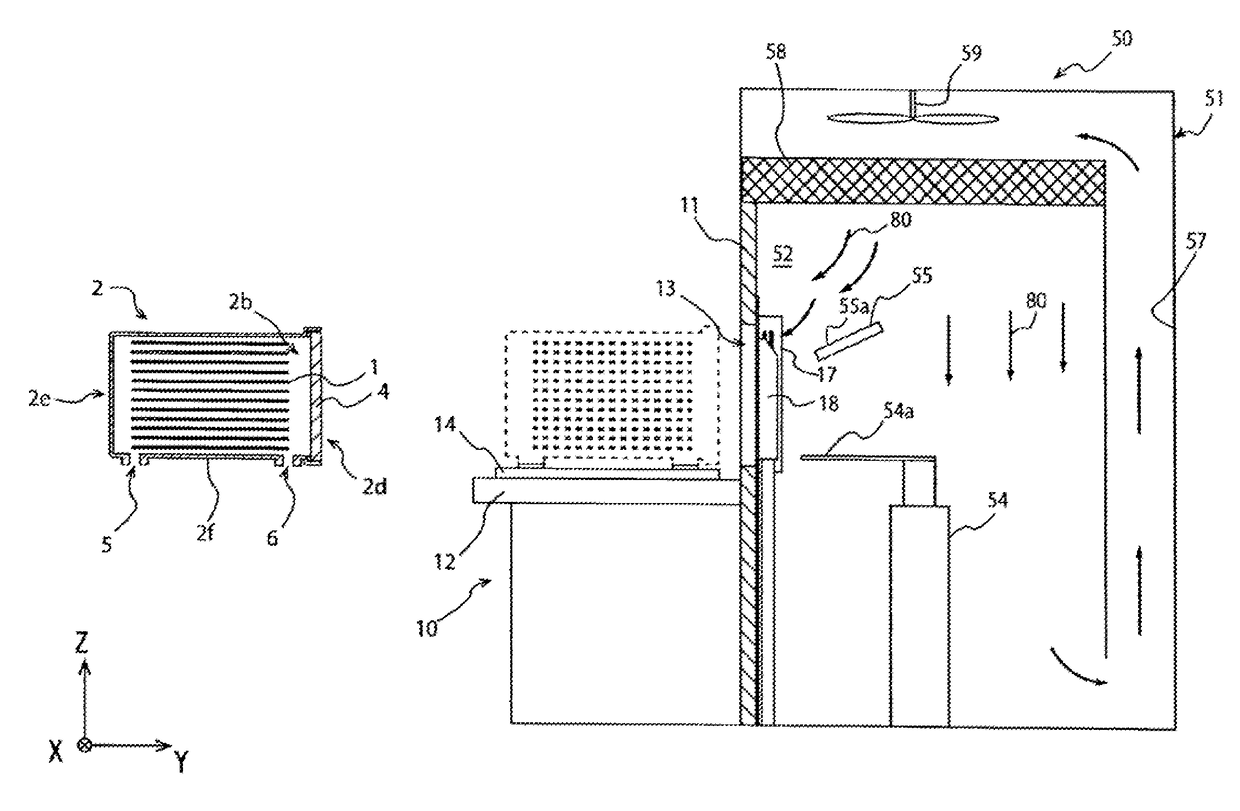
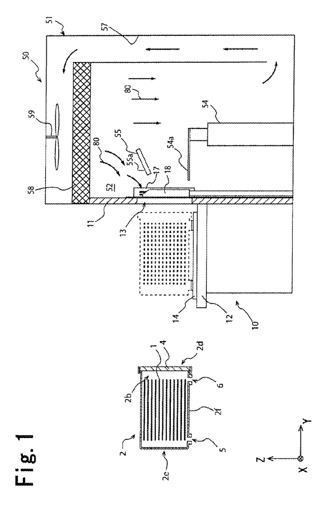
[0090]In a second cleaning step of the EFEM 150 shown in FIG. 6, an air or an inert gas is introduced from the introduction ports 160 arranged over the wafer transportation room 52. The air or inert gas introduced above the wafer transportation room 52 passes through the transportation room filter 58, flows into the wafer transportation room 52, and is thereafter discharged from the discharge ports 161 arranged below the wafer transportation room 52. A downward current by the transportation room fan 59 is also formed in the wafer transportation room 52 of the EFEM 150 in the same manner as First Embodiment shown in FIG. 1. The second cleaning step in the EFEM 150 shown in FIG. 6 demonstrates the same effect as the case of the EFEM 50 shown in FIG. 1 by introducing a part of the downward current 80 into the FOUP 2 using the current plate 55 and further carrying out the second cleaning step of the FOUP 2 for discharging the gas in the FOUP 2 from the first bottom nozzles 21.

third embodiment

[0091]FIG. 7 is a schematic cross sectional view showing an EFEM 250 of the present invention. The EFEM 250 is the same as the EFEM 50 shown in FIG. 1 except that a wafer transportation part 251 has a transportation room blow nozzle 262 as a gas blow means in addition to the current plate 55. The transportation room blow nozzle 262 is arranged in the wafer transportation room 52 and blows a cleaning gas from the wafer transportation room 52 toward the main opening 2b of the FOUP 2.

[0092]A cleaning gas is supplied from a pipe part not shown to the transportation room blow nozzle 262. The cleaning gas blown from the transportation room blow nozzle 262 may be an inert gas, a clean air, or the like in the same manner as the cleaning gas discharged from the second bottom nozzles 31, but preferably has a higher cleanliness than that of a gas in the wafer transportation room 52 constituting the downward current 80.

[0093]In this way, the method for introducing the gas from the main opening...

fourth embodiment

[0094]FIG. 8 is a schematic cross sectional view showing an EFEM 350 of the present invention. One of first bottom nozzles 321 of a load port part 310 of the EFEM 350 can introduce a cleaning gas from the first bottom hole 5 in Step S002 (first cleaning step) in FIG. 5, and can discharge a gas in the FOUP 2 from the first bottom hole 5 in Step S006 (second cleaning step).

[0095]The EFEM 350 having the first bottom nozzle 321 has a valve 342 capable of switching a state where the first bottom nozzle 321 is connected to the first pipe part 322 and a state where the first bottom nozzle 321 is connected to the second pipe part 332. The EFEM 350 having the bottom nozzle 321 can increase the number of introduction passages of the cleaning gas in the first introduction step, and thus can quickly clean the inside of the FOUP 2 before the main opening 2b is opened. In addition, both the introduction of the gas into the FOUP 2 and the discharge of the gas from the FOUP 2 can be carried out by...


PUM


Abstract

A controlling method for a wafer transportation part and a load port part on an EFEM includes a fixing step of fixing a container on an installation stand of the load port part, a first cleaning step of connecting a bottom nozzle of the load port part to multiple bottom holes formed on a bottom surface of the container and introducing a cleaning gas into the container and discharging a gas from the container via the nozzle, a connection step of connecting the container and the transportation room, and a wafer transportation step of transporting the wafer from the container to a processing room via the opening and the transportation room and transporting the wafer from the processing room to the container via the transportation room and the opening.

Description

BACKGROUND OF THE INVENTION[0001]1. Field of the Invention[0002]The present invention relates to a controlling method for a wafer transportation part and a load port part on an EFEM.[0003]2. Description of the Related Art[0004]In manufacturing steps of semiconductors, wafers are transported between respective processing apparatuses using a container called a FOUP or so. When the wafers are processed, the wafers in the container are transported from a FOUP to a processing room via an Equipment Front End Module (EFEM) equipped with the respective processing apparatuses.[0005]In the environment of a container housing wafers, it is preferred to maintain an inactive state and a cleanliness that exceed a predetermined level so as to protect the surfaces of the wafers from oxidation and contamination. As a method for improving an inactive state and a cleanliness of a gas in the transportation container, Patent Document 1 proposes a load port apparatus introducing a cleaning gas into a tran...

Claims


Application Information

Patent Timeline
IPC IPC(8): H01L21/677H01L21/02
CPCH01L21/02046H01L21/67703H01L21/6773H01L21/67781H01L21/67017H01L21/67393H01L21/67772H01L21/67775
Inventor OKABE, TSUTOMUHORIBE, HIDETOSHI
Owner TDK CORPARATION
Why Eureka
Try Eureka