
Sensor module for sensing forces to the head of an individual and wirelessly transmitting signals corresponding thereto for analysis, tracking and/or reporting the sensed forces

a sensor module and individual technology, applied in the field of sensing forces to the head of individuals, can solve the problems of not providing real-time information relating to the occurrence of impact events, and individuals engaged in a wide variety of physically demanding sports and activities risk brain or other serious injuries, so as to improve athletic performance, reduce risk, and make a game or activity safer

Inactive Publication Date: 2017-06-22
TRIAX TECH INC
View PDF4 Cites 16 Cited by
  • Summary
  • Abstract
  • Description
  • Claims
  • Application Information

AI Technical Summary

Benefits of technology

The present invention provides a system for accurately sensing and analyzing force events in real-time, which can help to protect players, coaches, and other participants in sports or other activities from potentially harmful impacts. The system uses a sensor module that is placed on the head or in a support that surrounds the head to transmit impacts to the head in real-time. The data collected from the sensor module can be used to better understand and improve an individual's performance through cognitive and balance evaluation tests. The system can also allow for the identification of players or others who may have taken severe or repeated impacts to the head, providing valuable information for medical attention. The sensor module is comfortable to wear and can be easily integrated with existing support devices. Overall, the system helps to increase athletic performance while decreasing risk, and provides valuable data for analysis and improvement.

Problems solved by technology

Individuals engaged in a wide variety of physically demanding sports and activities risk brain or other serious injuries resulting from impact, hyper-extension and other extreme movements or events.
They do not provide real-time information relating to occurrence of impact events to permit an individual being monitored to be removed from active play for the individual's safety.

Method used


Image

  • Sensor module for sensing forces to the head of an individual and wirelessly transmitting signals corresponding thereto for analysis, tracking and/or reporting the sensed forces
  • Sensor module for sensing forces to the head of an individual and wirelessly transmitting signals corresponding thereto for analysis, tracking and/or reporting the sensed forces
  • Sensor module for sensing forces to the head of an individual and wirelessly transmitting signals corresponding thereto for analysis, tracking and/or reporting the sensed forces

Examples


Embodiment Construction

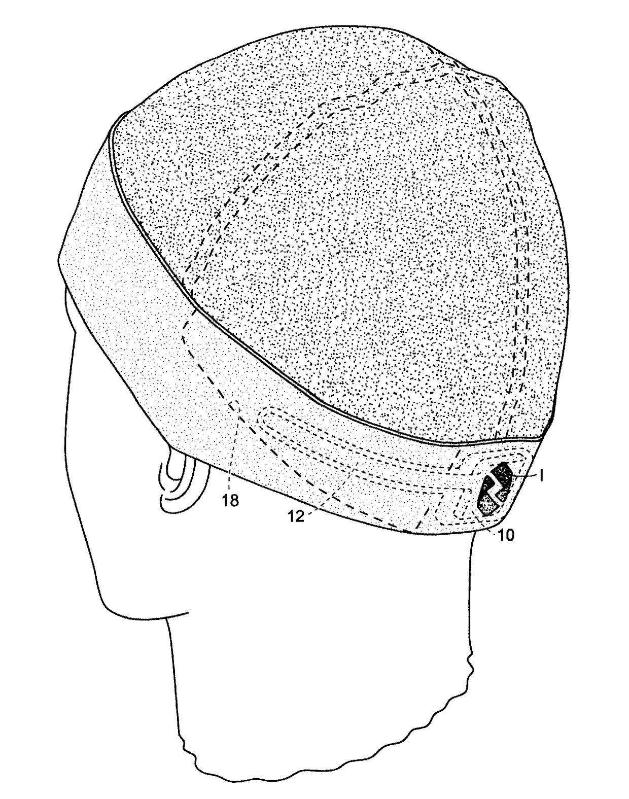
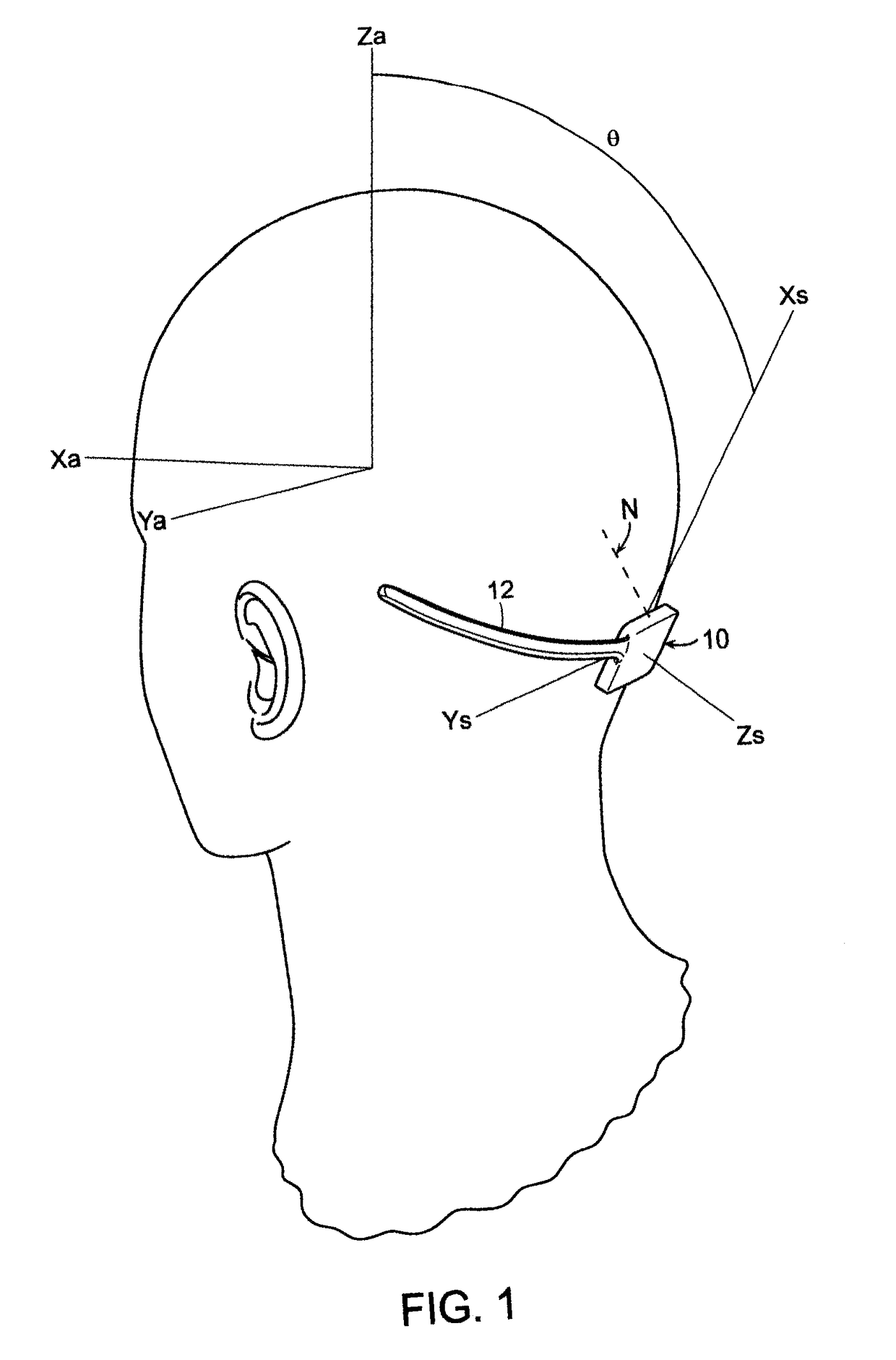
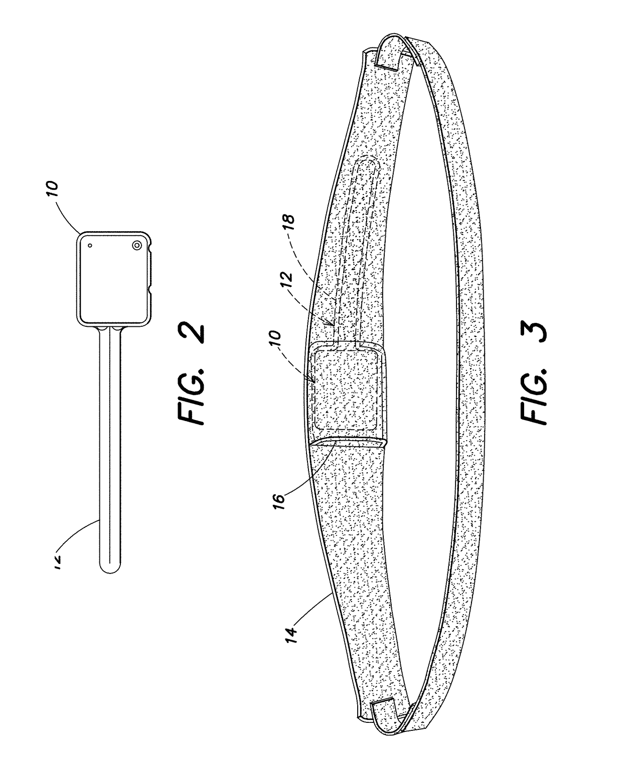
[0035]As shown in FIG. 1, a sensor module 10 in accordance with certain aspects of the present invention is typically a small, environmentally sealed device incorporating a sub GHz transceiver, a low power microprocessor, a 3-axis high g accelerometer, a 3-axis low g accelerometer, a 3-axis gyroscope, a non-volatile memory, a battery, a battery charger and other support circuitry. The sensor module 10 is sometimes referred to herein as a mobile sensor or a SIM or an impact monitor. The sensor module 10 is in substantial alignment with the median nuchal line of the occipital bone of the skull shown in dashed lines at N and, normally, between the inferior and superior nuchal lines. One embodiment utilizes a curved elongate antenna 12 extending from the sensor module housing toward the left side of the head. The anatomical axes denoted as Xa, Ya and Za, the sensor axes denoted as Xs, Ys and Zs and the subtended angle θ are illustrated in FIG. 1. The anatomical axes allow correlation wi...


PUM

PropertyMeasurementUnit
frequencyaaaaaaaaaa
forcesaaaaaaaaaa
flexibleaaaaaaaaaa

Abstract

Sensor module for sensing forces to the head of an individual and wirelessly transmitting signals corresponding thereto for analysis, tracking and / or reporting the sensed forces.

Description

CROSS-REFERENCE TO RELATED PATENT APPLICATIONS[0001]This application is a continuation in part of U.S. application Ser. No. 15 / 285,251 filed Oct. 4, 2016, entitled “SENSOR MODULE FOR SENSING FORCES TO THE HEAD OF AN INDIVIDUAL AND WIRELESSLY TRANSMITTING SIGNALS CORRESPONDING THERETO FOR ANALYSIS, TRACKING AND / OR REPORTING THE SENSED FORCES” which is a continuation of and claims priority under §120 to U.S. patent application Ser. No. 14 / 464,074, entitled “SENSOR MODULE FOR SENSING FORCES TO THE HEAD OF AN INDIVIDUAL AND WIRELESSLY TRANSMITTING SIGNALS CORRESPONDING THERETO FOR ANALYSIS, TRACKING AND / OR REPORTING THE SENSED FORCES,” filed Aug. 20, 2014. U.S. patent application Ser. No. 14 / 464,074, entitled “SENSOR MODULE FOR SENSING FORCES TO THE HEAD OF AN INDIVIDUAL AND WIRELESSLY TRANSMITTING SIGNALS CORRESPONDING THERETO FOR ANALYSIS, TRACKING AND / OR REPORTING THE SENSED FORCES,” filed Aug. 20, 2014, is a non-provisional of and claims priority under 35 U.S.C. §119(e) to U.S. Prov...

Claims


Application Information

Patent Timeline
Patent Type & Authority Applications(United States)
IPC IPC(8): A41D1/00G01L5/00A42B1/04A42B1/24A61B5/00A41D20/00G16H40/63
CPCA41D1/002A61B5/6803A61B5/6844A61B5/4088G08B29/046A42B1/041A42B1/242G01L5/0052A61B2562/0219A41D20/00A42B3/046G01P15/0891G01P15/18G08B21/0446A61B5/6831A61B5/1121A61B5/7275G16H40/63G16H40/67H05K2201/10098H05K1/165
Inventor MORGENTHAU, JUSTIN J.EPPLER, JR., WILLIAM G.HOLLINGSWORTH, WILLIAM D.
Owner TRIAX TECH INC
Learn More