Respiratory humidification system

a technology of respiratory gas and humidification system, which is applied in the field of respiratory gas humidification system, can solve the problems of greater heat loss in these regions and low temperatures, and achieve the effects of reducing the amount of condensate, improving the fluid characteristics of respiratory gas, and reducing the recirculation

Active Publication Date: 2017-06-22
FISHER & PAYKEL HEALTHCARE LTD
View PDF14 Cites 23 Cited by
  • Summary
  • Abstract
  • Description
  • Claims
  • Application Information

AI Technical Summary

Benefits of technology

[0007]A system is disclosed which may improve the fluid characteristics of the respiratory gas. Thus, it may reduce the amount of condensate. In some configurations, certain aspects can reduce the amount of condensate that flows back to the humidification chamber relative to the prior art. In some configurations, the angle of the elbow port can be increased to greater than 90° to reduce the recirculation that causes stagnant zones to occur and thereby reduce the condensate that forms in the system. Some embodiments include an insert or other structure shaped as a raised portion, which can be located near the sharp corner of the elbow port, to fill at least some of the dead space that is formed due to the recirculation of gases that occurs. The insert may reduce the likelihood of recirculation occurring in this region and thus may reduce the likelihood of stagnant zones forming. Therefore, regions of low temperature and low velocity gas are reduced, which reduces the amount of condensate that is generated. A raised portion may also act as barrier to any condensate that is formed and, as such, reduce the likelihood of condensate flowing back to the humidification chamber. A raised portion may be added to the port of the humidification chamber, may be part of the connector that inserts when the connector is connected to the port, or may be part of the conduit.
[0008]Some embodiments may comprise either the humidification chamber outlet port or the conduit being shaped in such a way that, or including geometries such that, gravity may reduce the likelihood of condensate reaching the humidification chamber.
[0009]Therefore, the improved system may reduce condensate formation between the outlet port of the humidification chamber and the proximal conduit end by improving flow characteristics. The improved system may provide mechanisms to reduce the likelihood of condensate flowing back to the humidification chamber.
[0011]In some such configurations, the raised portion inhibits liquid flowing from the conduit to the humidification chamber in use.
[0027]In some such configurations, the raised portion fills at least a lower portion of at least one of a horizontal portion of the outlet port, a conduit or a connector such that condensate is less likely to flow from the conduit into the humidification chamber.

Problems solved by technology

Delivery of humidified gases to patients exists in the prior art, however an aspect of at least one of the embodiments disclosed herein includes the realisation that there are problems with the delivery of this humidified gas.
Elbow ports can be used to form a horizontal connection between a humidification chamber and a conduit, which can cause recirculation to occur resulting in stagnant zones, which cause greater heat loss to occur in these regions.
This results in regions of low temperatures, which are more likely to form condensate.

Method used


Image

  • Respiratory humidification system
  • Respiratory humidification system
  • Respiratory humidification system

Examples


Embodiment Construction

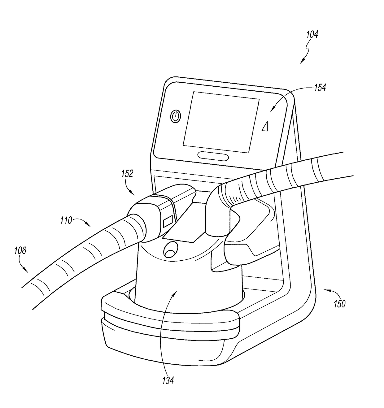
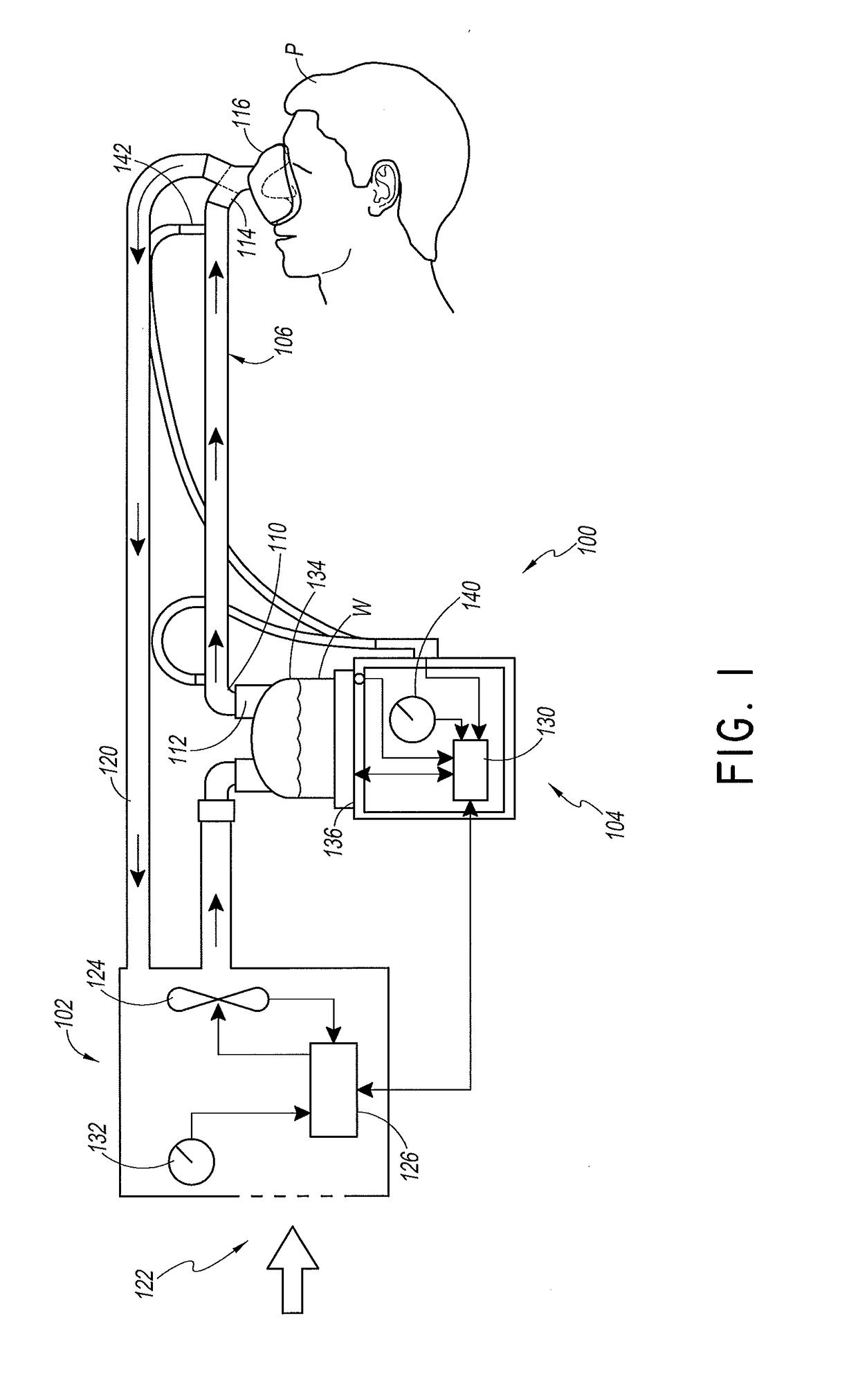
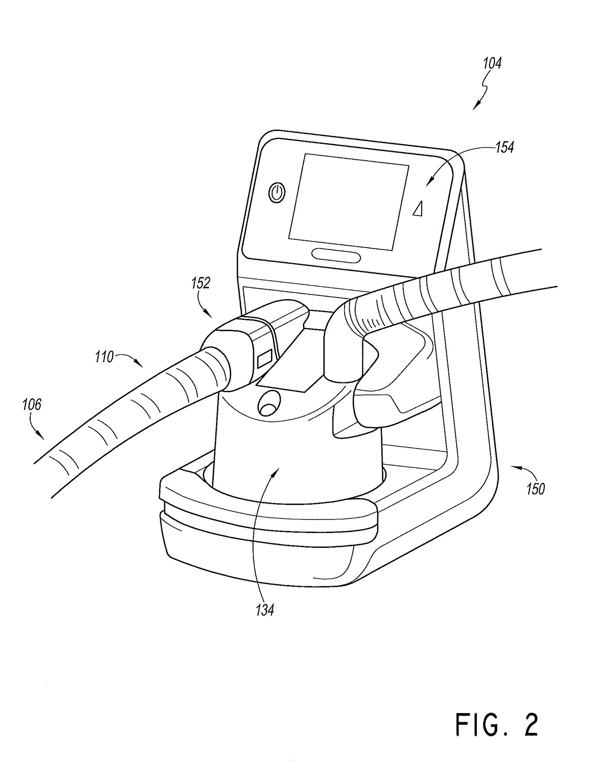
[0051]With reference to FIG. 1, a system 100 is illustrated that can be used to supply heated and / or humidified gases flow to a patient or other user. The system 100 can be configured to be a continuous, variable, or bi-level positive airway pressure (PAP) system, invasive or non-invasive respiratory assistance system, high flow respiratory therapy system, a surgical insufflation system, or a system providing other forms of medical gases. The system 100 may be readily adapted for other applications involving the supply of a heated and / or humidified gas flow to a user or patient, including but not limited to laparoscopy, ventilation support, and the like. Such applications may use alternative gases, operating parameters (e.g., flow, pressure, temperature, or humidity) and patient interfaces.

[0052]In the system 100, dry or relatively dry gases pass from a gases source 102 to a humidifier 104. The gases source 102 may be, for example, a ventilator or a blower.

[0053]The humidifier 104 c...


PUM


Abstract

A system provides warm, humidified gas to a patient via a patient interface. Horizontal connections can be used between the humidification chamber and conduit. To reduce the likelihood of condensate flowing back to the humidification chamber, or dead space or gases recirculation regions occurring within the gases flow path, a raised portion is positioned inside of the flow path to improve flow characteristics and to provide a barrier for condensate back flow. The raised portion also reduces the amount of condensate that is formed in the system and provides better flow characteristics for sensing purposes.

Description

INCORPORATION BY REFERENCE TO ANY PRIORITY APPLICATIONS[0001]Any and all applications for which a foreign or domestic priority claim is identified in the Application Data Sheet as filed with the present application are hereby incorporated by reference under 37 CFR 1.57.BACKGROUND[0002]Technical Field[0003]The present disclosure generally relates to humidification systems for providing humidified respiratory gases to patients. More particularly, the present disclosure relates to features that improve the performance of humidification systems.[0004]Description of the Related Art[0005]Respiratory humidification systems deliver heated and humidified gases to a patient via a patient interface. Patient interfaces can include a face mask, oral mask, nasal mask, nasal cannula, a combination of oral and nasal mask, tracheal mask, or the like. Gases leaving the humidification chamber to be delivered to a patient are at a temperature and relative humidity that may mimic the transformation of a...

Claims


Application Information

Patent Timeline
Patent Type & Authority Applications(United States)
IPC IPC(8): A61M16/08A61M16/10A61M16/16
CPCA61M16/0808A61M16/16A61M16/0875A61M2205/3368A61M16/1095A61M16/109A61M2205/50A61M16/0816A61M16/024F15D1/06F24F13/081
Inventor OSBORNE, HAMISH ADRIANHARWOOD, JONATHAN DAVIDROBERTSON, NATALIE MAY
Owner FISHER & PAYKEL HEALTHCARE LTD
Why Eureka
Try Eureka