
Damper device and starting device

a technology of starting device and hysteresis of elastic body, which is applied in the direction of vibration suppression adjustment, belt/chain/gearing, etc., can solve the problems of reducing the friction force that acts on the elastic body when the load is reduced, the damage to the hysteresis of the elastic body, so as to reduce the hysteresis

Active Publication Date: 2017-06-22
AISIN AW CO LTD
View PDF0 Cites 5 Cited by
  • Summary
  • Abstract
  • Description
  • Claims
  • Application Information

AI Technical Summary

Benefits of technology

The present invention provides a damper device with a dynamic damper that reduces hysteresis and ensures good strokes of torque transfer elastic bodies and vibration absorption elastic body without interference between them. By using a first abutment portion of a rotary element that abuts against an end portion of the torque transfer elastic body and a second abutment portion that abuts against an end portion of the vibration absorption elastic body, the centers of the two elastic bodies can be pushed together, reducing hysteresis and improving the expansion and contraction of the torque transfer elastic body.

Problems solved by technology

Unless the three types of abutment portions are disposed adequately so as not to interfere with each other, however, the stroke of the elastic bodies for torque transfer and the stroke of the vibration absorption elastic body of the dynamic damper may not be secured well, and the hysteresis of the elastic bodies for torque transfer, that is, a friction force that acts on the elastic bodies when the load is reduced, may become large.
Meanwhile, Patent Document 2 does not describe at all securing the stroke of the vibration absorption elastic body of the dynamic damper well or the hysteresis of the elastic bodies for torque transfer.

Method used


Image

  • Damper device and starting device
  • Damper device and starting device
  • Damper device and starting device

Examples


Embodiment Construction

[0027]Now, an embodiment of the present disclosure will be described with reference to the drawings.

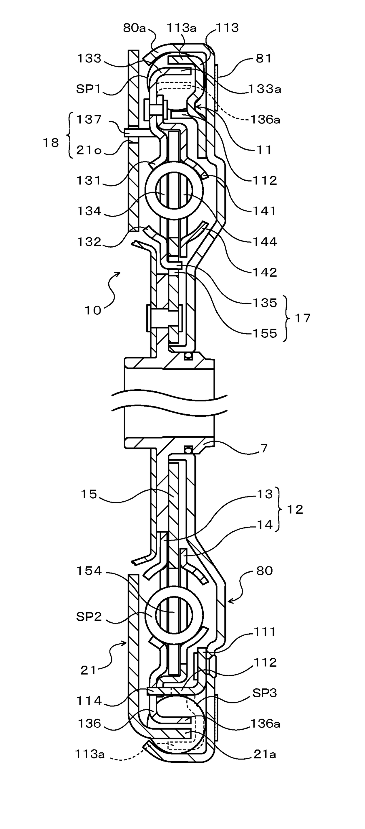
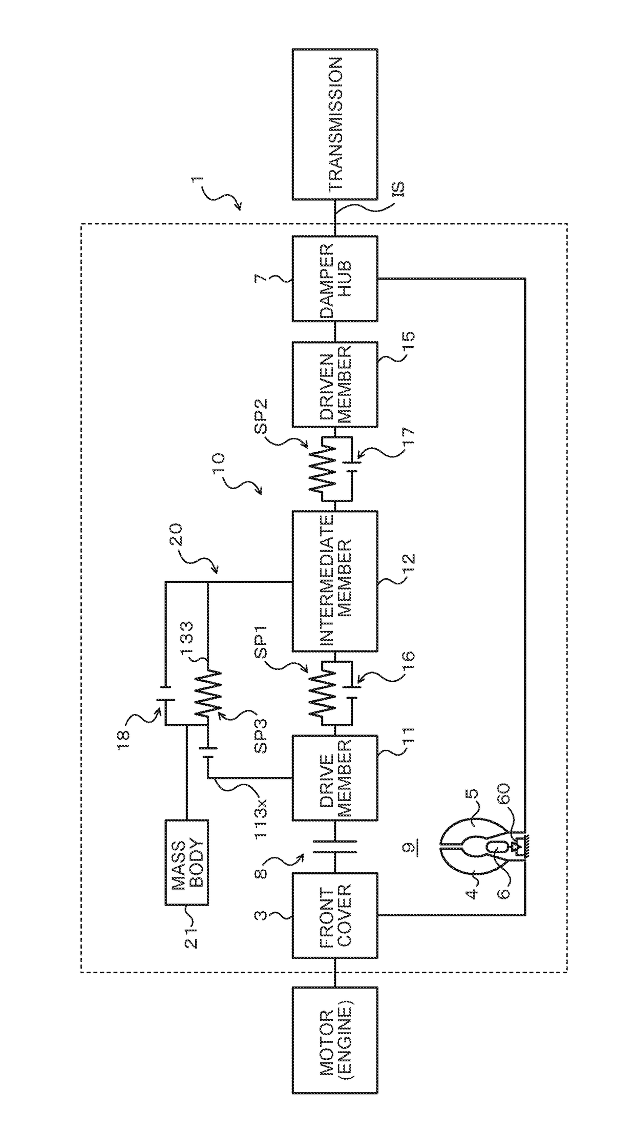
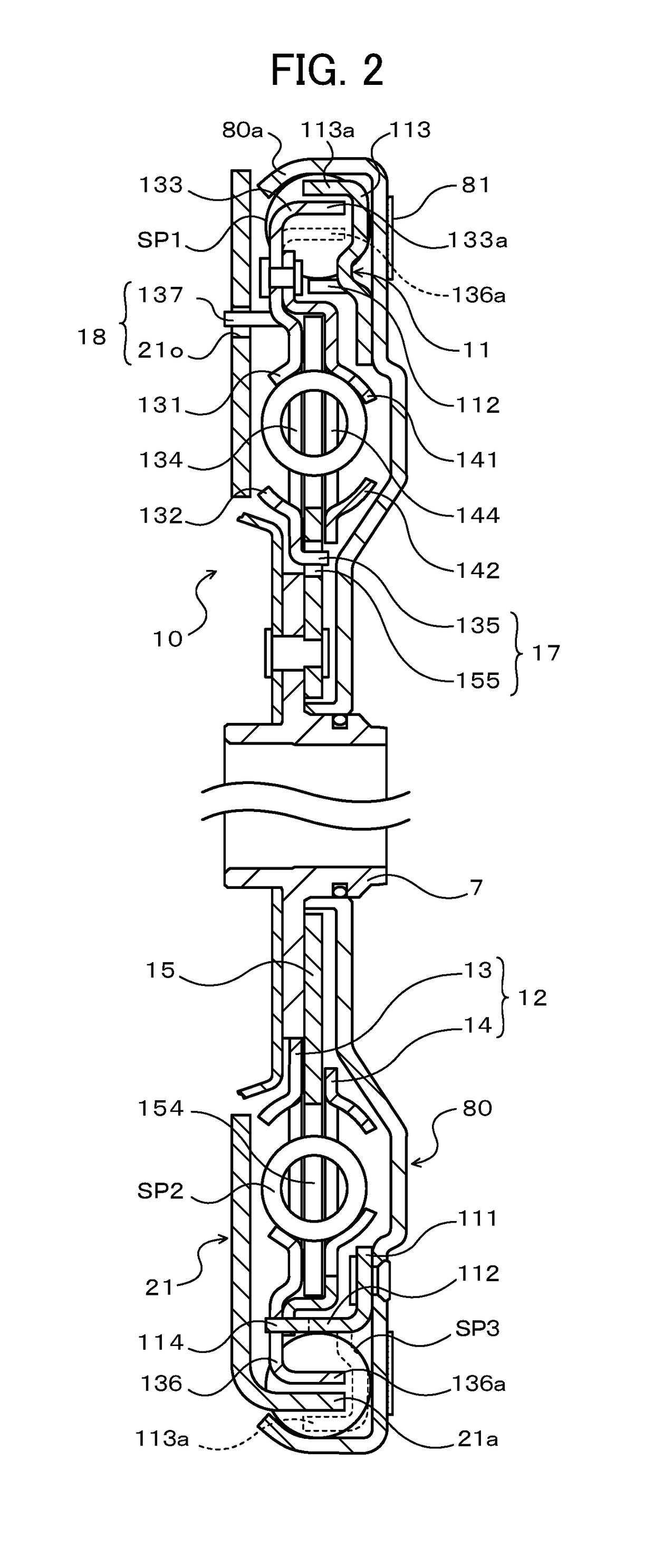
[0028]FIG. 1 is a schematic configuration diagram illustrating a starting device 1 that includes a damper device 10 according to an embodiment of the present disclosure. The starting device 1 illustrated in the drawing is mounted on a vehicle that includes an engine (internal combustion engine) that serves as a motor. In addition to the damper device 10, the starting device 1 includes: a front cover 3 that serves as an input member coupled to a crankshaft of the engine; a pump impeller (input-side fluid transmission element) 4 fixed to the front cover 3; a turbine runner (output-side fluid transmission element) 5 that is coaxially rotatable with the pump impeller 4; a damper hub 7 that serves as an output member coupled to the damper device 10 and fixed to an input shaft IS of a transmission that is an automatic transmission (AT) or a continuously variable transmission (CVT); a lock-u...


PUM


Abstract

A damper device has a dynamic damper that includes a mass body and vibration absorption springs that couple the mass body and an intermediate member to each other. The vibration absorption springs are arranged side by side with outer springs in the circumferential direction. The mass body has spring abutment portions that abut against end portions of the vibration absorption springs. The intermediate member has first outer spring abutment portions that abut against end portions of the outer springs and second outer spring abutment portions that abut against end portions of the vibration absorption springs on the radially inner side with respect to the spring abutment portions. The first outer spring abutment portions extend toward the radially outer side with respect to the second outer spring abutment portions.

Description

TECHNICAL FIELD[0001]The present disclosure relates to a damper device that has a plurality of rotary elements that include at least an input element and an output element, a torque transfer elastic body that transfers torque between the plurality of rotary elements, and a dynamic damper coupled to one of the plurality of rotary elements, and to a starting device that includes the damper device.BACKGROUND ART[0002]There has hitherto been known a damper device that includes a first elastic body that transfers torque between an input element and an output element, a second elastic body disposed on the inner side of the first elastic body to transfer torque between the input element and the output element, and a dynamic damper that has a vibration absorption elastic body coupled to any of rotary elements that constitute the damper device and a mass body coupled to the vibration absorption elastic body (see Patent Document 1, for example). In the damper device, the vibration absorption ...

Claims


Application Information

Patent Timeline
Patent Type & Authority Applications(United States)
IPC IPC(8): F16F15/123F16H45/02
CPCF16F15/12353F16H2045/0221F16H45/02F16F15/12366F16F15/1428F16H2045/0231F16H2045/0263
Inventor ITO, KAZUYOSHIARAKI, KEIZOUENO, MAKOTOHIRAI, YUICHIROWAJIMA, MASAKIKANYAMA, YUJITSUDA, KOTARO
Owner AISIN AW CO LTD
Features
  • Generate Ideas
  • Intellectual Property
  • Life Sciences
  • Materials
  • Tech Scout
  • Unparalleled Data Quality
  • Higher Quality Content
  • 60% Fewer Hallucinations
Learn More