
Method and system for non-destructive rail inspection

a non-destructive and rail inspection technology, applied in the direction of railway signalling and safety, railway components, magnitude/direction of magnetic fields, etc., can solve the problems of rail tracks subject to wear and damage, extreme train derailment, wear and damage, etc., and achieve the effect of efficient identification of defects on the railway track

Inactive Publication Date: 2017-06-22
PURETECH VENTURES
View PDF6 Cites 16 Cited by
  • Summary
  • Abstract
  • Description
  • Claims
  • Application Information

AI Technical Summary

Benefits of technology

The invention is a method and system for inspecting and analyzing metal rails, such as those in a railway track. It uses magnetometers to efficiently identify defects on the rail and to discriminate between different types of damage or defects within the rail. The method can also track changes in the rail over time by measuring and recording magnetic field variations. The invention helps to identify and locate defects on a loaded railway track and reject false positive results.

Problems solved by technology

Rail tracks are subject to wear and damage, due to a variety of factors including the physical contact over time between wheels of the railroad car or other vehicles and the rail track.
Rail wear and damage can produce train derailment in extreme cases, if not detected in time.
In order to identify and analyze rail deterioration, conventional inspection methods including visual, electromagnetic, ultrasound, and Electromagnetic Acoustic Transducer (EMAT) techniques have proven effective in some situations, but these methods have some important limitations.
Many of the conventional inspection methods do not allow for quick and efficient analysis.
Consequently, mishaps and derailments may occur before adequate inspections have had the opportunity to be performed along portions of a rail track.
However, the prior art does not teach how to discriminate between types of defects or damage or in the case of rail inspection, the relative position of a defect or damage within a rail track.

Method used


Image

  • Method and system for non-destructive rail inspection
  • Method and system for non-destructive rail inspection
  • Method and system for non-destructive rail inspection

Examples


Embodiment Construction

[0029]In the following description, similar features in the drawings have been given identical reference numerals where appropriate. Terms such as “top” and “bottom”, “first” and “second”, or “right” and “left” or an identification of a particular x, y or z-axis may be used to identify opposing ends or different configurations or sides of structures. Such terms are used for illustration purposes and are not intended to limit the present disclosure.

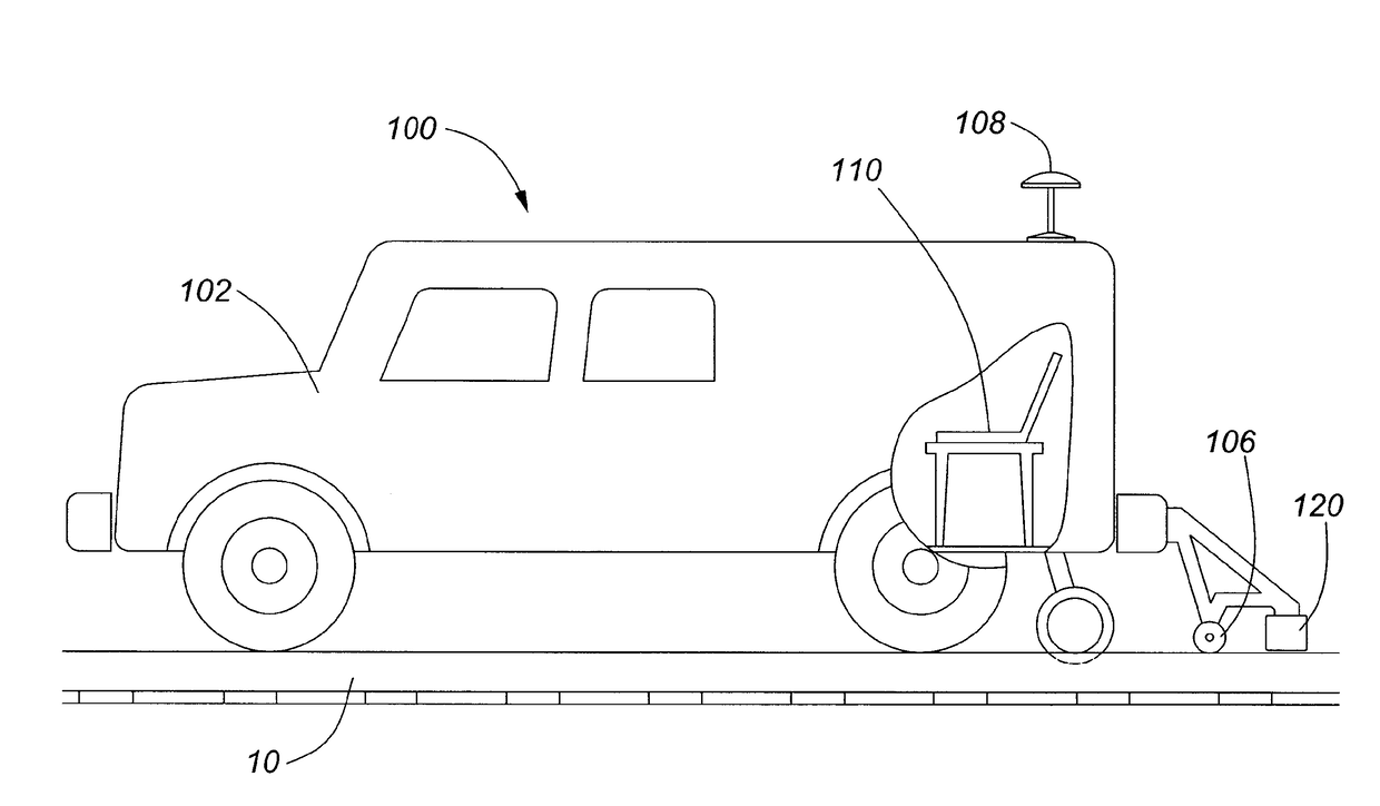
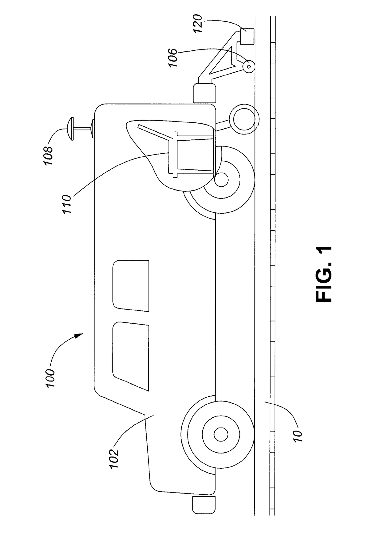
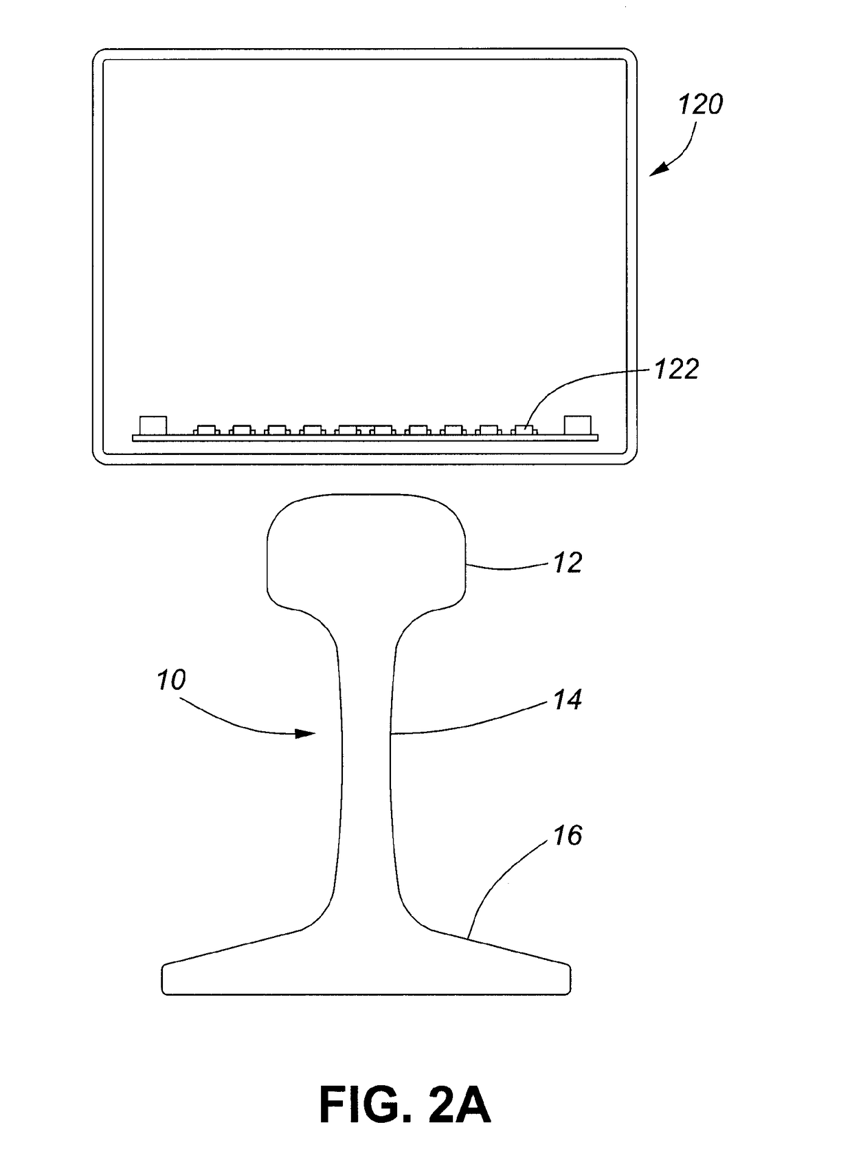
[0030]Referring to FIG. 1 is an embodiment of a system 100 for identifying and locating defects in a railway track, or a metal rail 10. The system includes an apparatus 120 with at least one magnetic sensor such as a magnetometer 122 (as shown in FIG. 2) which is moveable along a length of the rail for measuring the magnetic fields of the metal rail, and a processor, as illustrated by a computer 110. The computer 110 includes memory such as a non-transitory computer readable medium which stores instructions for implementing certain aspects...


PUM

PropertyMeasurementUnit
vertical distanceaaaaaaaaaa
distanceaaaaaaaaaa
distancesaaaaaaaaaa

Abstract

The present invention relates to a method for identifying and locating a defect in a metal rail, and includes the steps of positioning a first magnetic sensor at a distance above a rail, the first magnetic sensor being configured to measure a magnetic field of the rail; advancing the sensor along a length of the rail; sampling magnetic field measurements; determining multiple magnetic field gradients over different pluralities of samples; identifying a defect in the rail based on a change in one or more of the magnetic field gradients; and determining a position of the defect at a particular distance from the magnetic sensor based on a degree of variation in the magnetic field gradients.

Description

RELATED APPLICATIONS[0001]This application claims priority based on U.S. App. No. 61 / 938,429, entitled “USE OF MAGNETIC METHODS TO INSPECT RAIL TRACK” filed on Feb. 11, 2014, which is hereby incorporated by reference.TECHNICAL FIELD[0002]The present invention relates to non-destructive methods and systems for analyzing metals rails, such as rails of railway tracks, for defects. In particular, the invention relates to a method and a system for identifying and locating defects on a railway track.BACKGROUND[0003]Many countries have extensive networks of railways that comprise several kilometres of railway tracks. For instance, the United States has a network of over 250,000 km, of rail tracks. These rail tracks service freight and passenger lines. Optimal operation and maintenance of the railway infrastructure ensures safe and timely delivery of goods and passengers.[0004]Rail tracks are subject to wear and damage, due to a variety of factors including the physical contact over time be...

Claims


Application Information

Patent Timeline
Patent Type & Authority Applications(United States)
IPC IPC(8): G01N27/82B61L23/04B61K9/10
CPCG01N27/82B61L23/044B61K9/10G01R33/022
Inventor PAULSON, PETER O.
Owner PURETECH VENTURES
Learn More