Method, Controller, Program, and Data Storage System for Performing Reconciliation Processing

a data storage system and data processing technology, applied in the field of data storage, can solve problems such as the inability to perform automated or semi-automated analysis, the difficulty of data reconciliation research topics, and the discovery of hidden patterns and distiling knowledge out of data, so as to reduce processing overhead

Inactive Publication Date: 2017-06-22
FUJITSU LTD
View PDF6 Cites 8 Cited by
  • Summary
  • Abstract
  • Description
  • Claims
  • Application Information

AI Technical Summary

Benefits of technology

[0014]Embodiments provide a mechanism for comparing portions of graph data and specifically for comparing vertices within those portions. Comparisons of vertices form the basis of reconciliation processing, and reconciliation processing can be considered to comprise a series of comparisons between vertices. The mechanism for comparing vertices in embodiments is based on the propagation of events in the graph, which is distinct from existing semantic-based mechanisms. Embodiments utilize the assumption that correlated vertices in different graphs will respond in the same or a similar way to equivalent processing events. That is, that functional semantics based on data utilization can be used as a basis for comparing vertices. Therefore, by observing the behavior of vertices in response to processing events it is possible to compare vertices and identify when vertices in the source data graph have equivalent vertices in the target data graph.
[0022]The event propagation mechanism is configured to respond to a processing event by triggering the execution of one or more event handlers at respective associated vertices. Furthermore, the event propagation mechanism may be configured to respond to the execution of an event handler at a vertex by triggering further executions of event handlers at other vertices. In that way, a single processing event can propagate and cause effects (event handler executions) at vertices other than those modified by the single processing event.
[0028]The comparisons between pairs of vertices are the basis of reconciliation processing, and provide a measure which may be used to assert equivalence links between pairs of vertices, thus reconciling the data graphs. It may be that each vertex of the source data graph is compared with each vertex of the target data graph. On the other hand, some logic or filtering may be applied before such comparisons are performed, in order to reduce the processing burden of the reconciliation processing.
[0031]Advantageously, the data identifying each vertex at which a consequential processing event occurred as a consequence of the execution of a processing event provides a per-vertex listing of the processing events to which consequential processing events were performed at the vertex. Such a listing can perform the basis of a full or preliminary comparison between pairs of vertices at little processing cost.
[0043]Advantageously, a simple determination of whether or not consequential processing events were executed at each of a pair of vertices (one from each data graph) in response to executions of the same processing event in the different data graphs, can act as a filter to exclude a pair of vertices from further comparison processing. Thus, a filtering effect is achieved and overall processing overheads are reduced. In other words, if a consequential processing event is carried out at each of a pair of vertices in response to executions of the same processing event or of the same type / category of processing event, then that pair of vertices are selected for further comparison processing. Otherwise, the pair is excluded from further comparison processing, and the pair of vertices will not be reconciled with one another.
[0050]Advantageously, limiting the set of processing events to the n most frequently executed processing events provides a means by which to reduce the processing overhead imposed by the reconciliation processing. Furthermore, it may be that the reconciliation processing is carried out in an incremental manner, with first the n most frequently executed processing events being used, and then, at a subsequent system idle time, reconciliation processing being carried out with a larger set of processing events. It is assumed in the above that n is a positive integer. The value of n may be predetermined by a database administrator, or may be a condition of the reconciliation request. Alternatively, it may be that n is adaptable according to available system resources, with n being proportional to the amount of available processing resources. The list of processing events executed on the target data graph may be obtained from a system log, or may be derivable by analyzing the records maintained by the centralized or local event propagation managers.

Problems solved by technology

The enormous volume of graph data available creates potential for automated or semi-automated analysis that can not only reveal statistical trends but also discover hidden patterns and distil knowledge out of data.
The decentralized nature of such data leads to the issue that often many data sources use different references to indicate the same real world object.
Data reconciliation is a challenging research topic in very large databases and large-scale knowledge bases.
It is hard for such information to dynamically reflect how data are leveraged in applications.
The processing required to identify any vertices which are semantically equivalent is a significant performance overhead in data graph systems.
It is difficult for static information to dynamically reflect how data are leveraged by applications.
Depending on the implementation details, it may be that the usage of the target data graph varies significantly over time, so that processing events which were commonly executed for a period of time are no longer executed very commonly, and hence do not accurately reflect the current status of the graph.

Method used


Image

  • Method, Controller, Program, and Data Storage System for Performing Reconciliation Processing
  • Method, Controller, Program, and Data Storage System for Performing Reconciliation Processing
  • Method, Controller, Program, and Data Storage System for Performing Reconciliation Processing

Examples


Embodiment Construction

[0072]Reference will now be made in detail to the embodiments, examples of which are illustrated in the accompanying drawings, wherein like reference numerals refer to the like elements throughout. The embodiments are described below to explain the present invention by referring to the figures.

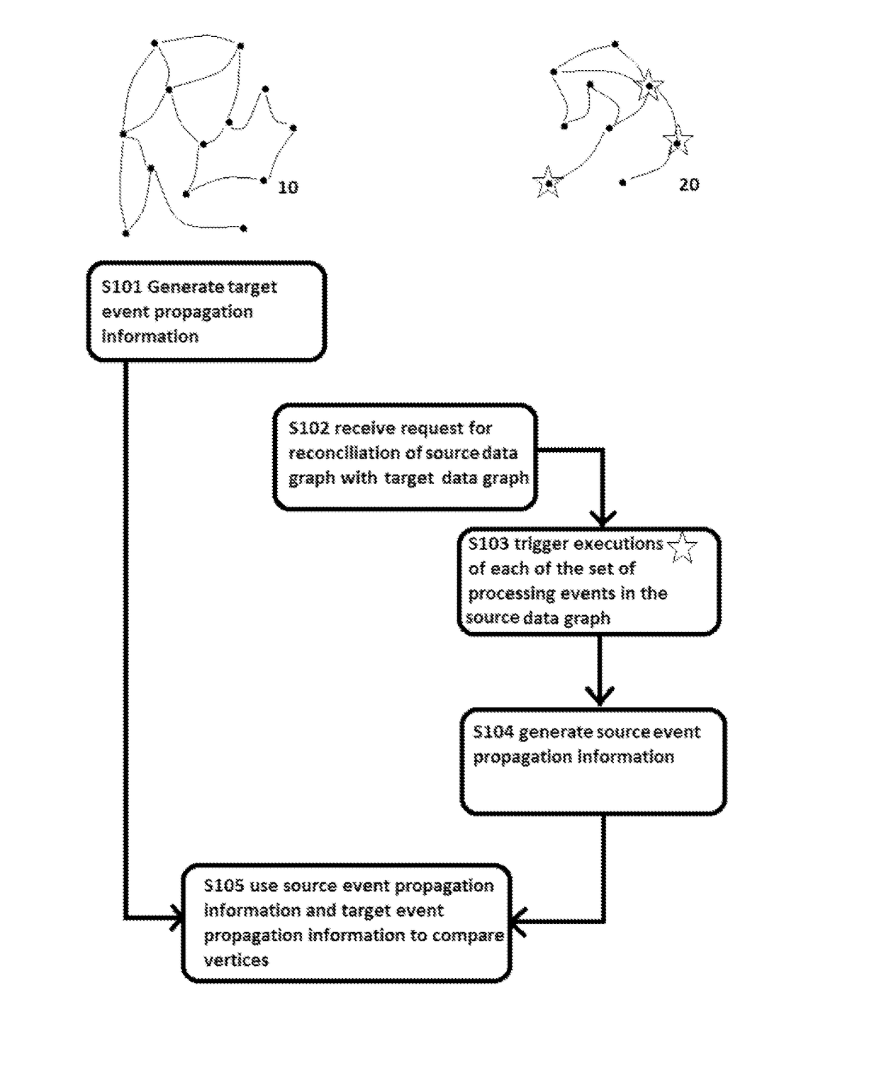
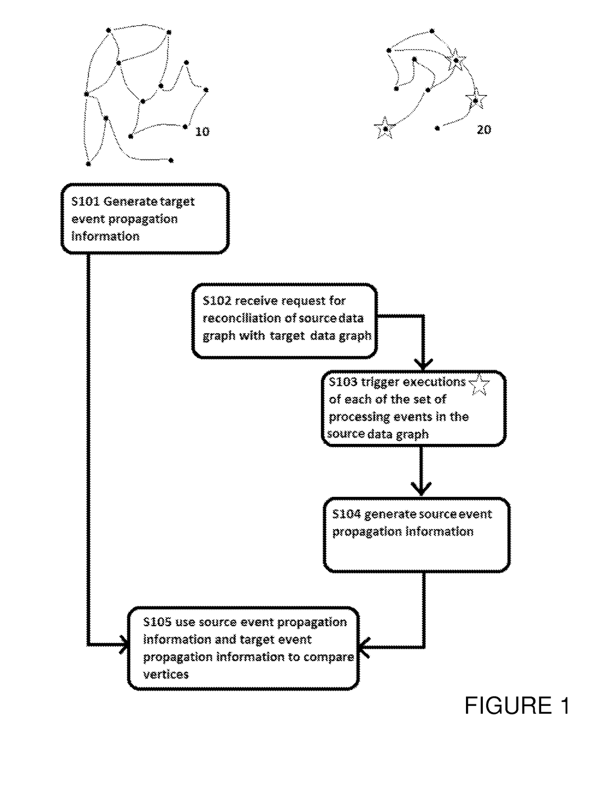
[0073]FIG. 1 is a diagram illustrating the steps in a procedure executable by a computer. Representations of a target data graph 10 and source data graph 20 are included for illustrative purposes. The geometric representation of a data graph such as that illustrated is only one of many possible ways in which a data graph may be represented. For example, the data graph is encoded with an underlying data structure, such as RDF triples. Furthermore, labels (not illustrated) are attributed to the vertices (dots) and interconnections or edges (lines). The size and geometry of the illustrated data graphs is arbitrary.

[0074]The procedural flow of FIG. 1 includes five steps S101 to S105. The arrows il...


PUM


Abstract

A method for reconciling a source data graph with a target data graph, the source graph and the target graph each comprising: and a interconnections, the interconnections each connecting two vertices from and representing a relationship between the connected vertices. The method comprises: generating target event propagation information representing the propagation pattern of executions of each of a set of processing events in the target graph; receiving a request to reconcile the source and graph, and in response to the request, triggering the executions of each of the set in the source graph; generating source event propagation information representing the pattern of each of the executions triggered in the source graph; and using the target event propagation information and the source event propagation information to assess the similarity of pairs of vertices comprising one vertex from each of the source graph and the target graph.

Description

CROSS-REFERENCE TO RELATED APPLICATIONS[0001]This application claims the benefit of European Application No. 14193757.3, filed Nov. 18, 2014, the disclosure of which is incorporated herein by reference.BACKGROUND[0002]1. Field[0003]The present invention lies in the field of data storage and the associated processing. Specifically, embodiments of the present invention relate to the performance of reconciliation processing of vertices in graph data. The reconciliation processing is intended to reconcile heterogeneity between semantically equivalent vertices in the graph.[0004]2. Description of the Related Art[0005]The enormous volume of graph data available creates potential for automated or semi-automated analysis that can not only reveal statistical trends but also discover hidden patterns and distil knowledge out of data. Formal semantics plays a key role in automating computation-intensive tasks. While there are varying opinions on how semantics are best captured, it is widely reg...

Claims


Application Information

Patent Timeline
Patent Type & Authority Applications(United States)
IPC IPC(8): G06F17/30
CPCG06F17/30958G06N5/022G06F16/24575G06F16/24573G06F16/9024G06F16/24578G06F16/93
Inventor HU, BOBUTT, AISHA NASEERMENDAY, ROGER
Owner FUJITSU LTD
Why Eureka
Try Eureka