
Eureka
For R&D, Eureka makes reading and utilizing patents & technical documents easy.
Eureka AIR
Designed for self-driven R&D workflows. Generate viable solutions, solve complex R&D challenges, empower your innovation with AI.

Eureka Materials
Designed for material experts only. Revolutionize your material R&D, from search, analyze, to developing new materials.

TechResearch
Generate reliable direction feasibility study reports for your R&D in just a few steps.

TechSeek
Discover and master advanced knowledge NOW. Basics, ideas, possibilities, all at once.

TechMind
As an expert in R&D Theories, TechMind can generates customized viable solutions instantly.

TechRisk
Analyze your overall solution with one click, know your potential R&D risks in advance.

TechMonitor
Get weekly tech updates, stay abreast of the latest tech innovations and key insights.
Image forming apparatus and recording medium
- Summary
- Abstract
- Description
- Claims
- Application Information
AI Technical Summary
Benefits of technology
Problems solved by technology
Method used
Image

Examples
first embodiment
1. First Embodiment
1-1. Device Configuration
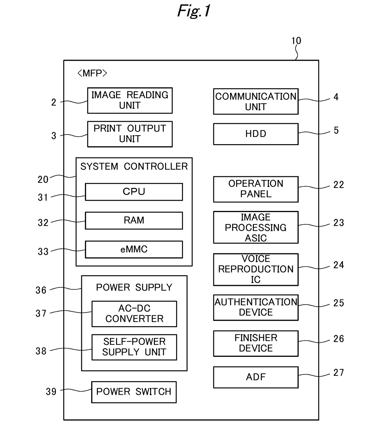
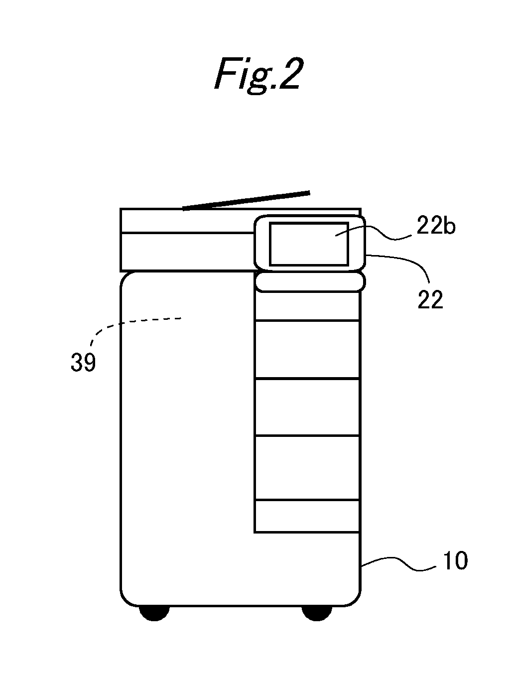
[0028]FIG. 1 is a diagram showing function blocks of an image forming apparatus 10. This description exemplifies an MFP (Multi-Functional Peripheral) as the image forming apparatus 10. Further, FIG. 2 is an outer appearance view of the MFP 10.
[0029]The MFP 10 is a device equipped with a scan function, a copy function, a facsimile machine function, a box storage function, and the like (the device is also referred to as a multi-functional peripheral). Specifically, as shown in the function block diagram of FIG. 1, the MFP 10 is equipped with an image reading unit 2, a print output unit 3, a communication unit 4, an HDD (Hard Disk Drive) 5, a system controller 20, an operation panel unit 22, an image processing ASIC 23, a voice reproduction IC 24, an authentication device 25, a power supply 36, and the like, and the MFP 10 realizes various functions by causing these units to operate complexly.
[0030]The image reading unit 2 is a processing uni...
second embodiment
2. Second Embodiment
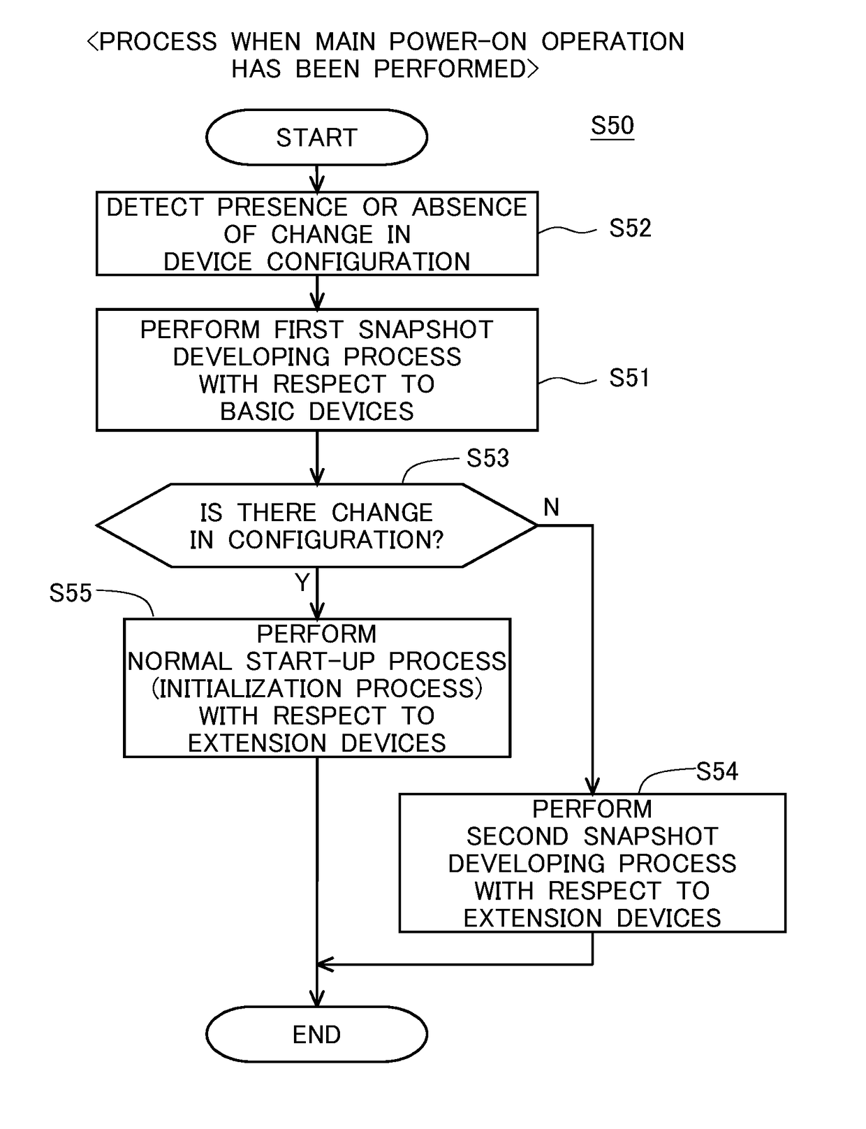
[0090]In the above first embodiment, as shown in FIG. 5 and the like, a device-configuration-change detection process (step S52) is performed after the first snapshot developing process (step S51) is performed; however, the present invention is not limited to that order. For example, in the opposite order, the first snapshot developing process (step S51) may be performed after the device-configuration-change detection process (step S52) is performed. In the second embodiment, such an aspect will be described.
[0091]The second embodiment is an modified example of the first embodiment. In the following, the difference from the first embodiment will be mainly described with reference to FIG. 9 and the like. Note that FIG. 9 is a flowchart showing an operation according to the second embodiment.
[0092]As shown in FIG. 9, in the second embodiment, the device-configuration-change detection process (step S52) is first performed (time T31 to time T32 in FIG. 10), and after...
PUM
 Abstract
Description
Claims
Application Information
 - R&D Engineer
- R&D Manager
- IP Professional
- Industry Leading Data Capabilities
- Powerful AI technology
- Patent DNA Extraction
Browse by: Latest US Patents, China's latest patents, Technical Efficacy Thesaurus, Application Domain, Technology Topic, Popular Technical Reports.
© 2024 PatSnap. All rights reserved.Legal|Privacy policy|Modern Slavery Act Transparency Statement|Sitemap|About US| Contact US: help@patsnap.com